OWNER’S MANUAL INSTALLATION INSTRUCTIONS WINEGARD RV Digital Satellite System with RS-1000 Antenna Model RD-4610 U.S. PATENTS 5,532,710 and 5,554,998 Made in U.S.A. IMPORTANT: INSTALL POINT OF BASE TOWARD FRONT OF VEHICLE! Winegard Company • 3000 Kirkwood St. • Burlington, IA 52601-2000 319/754-0600 • FAX 319/754-0787 Printed in U.S.A. © Winegard Company 2001 2451142 Rev.
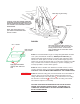
INSTALLATION & ASSEMBLY STEP 1. Choose a location for antenna that will allow it to rest in travel position with antenna pointing toward rear of vehicle and raise and rotate without interfering with other roof-mounted equipment. Make sure inside ceiling area is clear where ceiling plate will mount. NOTE: Figure 1 shows minimum distance (10") antenna should be located from edge of vehicle roof.
STEP 3. Attach reflector to backup assembly as shown in Figure 2. STEP 4. Attach RS-1000 antenna to elevating tubes, see Figure 2, using the two Eclips and pins provided. Attach coax cable to F-jack on antenna, slide weather boot over boot collar. RS-1000 Antenna Reflector Attach coax cable to F-jack on antenna, slide weather boot over boot collar. (4) 5/16-18 x 5/8" Flat Head Bolt Attach RS-1000 to elevating tubes using E-clips and pins supplied.
STEP 5. The mount is designed to fit roofs 1" to 4 3/4" thick. If roof is less than 4 3/4" thick, cut elevating shft and directional handle to size. (See table below.) If roof is more than 4 3/4" thick, the RP-2000 Thick Roof Kit is required. See page 15, A for chart. CAUTION: IF YOU ARE USING THE RW-1000 ROOF WEDGE, ADD 1/2" TO ELEVATING SHAFT LENGTH GIVEN BELOW, BUT NOT TO THE DIRECTIONAL HANDLE.
Cable clamp on gear housing. CAUTION: DO NOT GET SEALING COMPOUND ON BEARING SURFACE BETWEEN BASE PLATE AND ROTATING GEAR HOUSING. DO NOT PAINT TOP OF BASE PLATE OR AROUND ROTATING GEAR HOUSING. Cable Ties NOTE: Apply sealant approved for your vehicle roof between Base Plate and roof of vehicle. 3" min. FIGURE 3 #10 x 1" Screws Make sure cable entry is sealed Apply approved sealant under lip and cable roof hole INSIDE RV Attach cable clamp here.
CAUTION: After INITIAL INSTALLATION, the antenna SHOULD ROTATE APPROXIMATELY 360 DEGREES FROM TRAVEL POSITION. The pointer on the DIRECTIONAL HANDLE should point towards the ROTATION CLAMP when in TRAVEL POSITION.
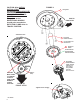
OPERATION STEP 1. Using a compass, determine which direction is North. It is recommended that you step outside to perform this step. Standing in or near coach/RV can give you an incorrect reading. The more accurately you determine North, the easier it will be to find the satellite(s). Directional Handle Elevating Crank Directional Handle Pointer Directional Dial FIGURE 5 Rotation Clamp STEP 2. Move rotation clamp to the LOCK position. STEP 3.
TUNING ANTENNA FOR BEST PICTURE STEP 8. Your receiver should indicate it is receiving a signal. To tune your antenna for the best picture, slowly move the antenna left, then right until you have found the position that gives the highest signal strength. It is important to turn the antenna slowly; since the signal is digital the receiver takes a few seconds to lock on. STEP 9. Place rotation clamp in the LOCK position. This prevents the antenna from moving and losing the signal. STEP 10.
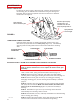
Coax downlead from satellite antenna Coax downlead from RS-1000 TV Satellite Receiver Power Supply VCR A-B Switch FIGURE 6 Coax downlead from satellite antenna Coax downlead from RS-1000 TV Satellite Receiver Power Supply Video Switch VCR Set 2 FIGURE 7 Coax downlead from satellite antenna Satellite Receiver Coax downlead from RS-1000 TV Power Supply VCR FIGURE 8 9
MAINTENANCE MOUNT LUBRICATION To lubricate the mount, apply a liberal amount of silicone spray lubricant to the elevating gear, the lubricant hole and between the gear housing and baseplate. Run the antenna up/down and rotate the antenna to distribute the lubricant. See Figure 9. Remove cap and spray lubricant into the lubricate hole. Be sure place cap firmly back on.
TROUBLE SHOOTING NO PICTURE 1. Check that you have a clear line of sight to the satellite (no trees, buildings, etc.). 2. Check that you have the TV set tuned for the correct channel 3 or 4 (same channel as output of receiver). 3. Double check that you have entered the correct zip code into the receiver. If zip code is wrong, this can cause you to look in the wrong direction/elevation for the satellite. 4. Check connections at receiver, TV, and antenna. 5. Check TV.
PARTS LIST (not all parts listed due to space constraints) 46cm (18") Reflector, White P.N. 2745304 (4) 5/16" Hex Nut P.N. 2160230 (4) 5/16" Flat Washer P.N. 2160027 (2) 1/4-20 Hex Nut, Nylock P.N. 2160220 Backup P.N. 2745348 (4) 1/4" Flat Washer P.N. 2160039 (5) E-Clip P.N. 5160818 (2) 1/4-20 X 1.75" Hex Bolt P.N. 2160238 Digital Elevation Device, If attached the 1/4-20 x 1.75 Hex Bolts are replaced with 1/4-20 x 2" Hex Bolts (3) 1/4 x 2-5/16" Pin P.N. 2160814 Bumper Assembly P.N.
PARTS LIST Upper Elevating Tub P.N. 3506032 RS-1000 Mount Adapter P.N. 2200114 Bolt P.N. 3200350 Lower Elevating Tube P.N. 3506033 LNBF is attached to pivot arm with: 1/4-20 x 1/2" Cap Screw P.N. 2160240 1/4-20 Nylock Hex Nut P.N. 2160220 LNBF P.N. 2780161 (2) 1/4" Washer P.N. 2160024 (4) Flat Head Bolts (white) P.N. 2160361 (3) 1/4 x 2-5/16" Pin P.N. 2160814 (2) Travel Link P.N. 2745050 LNBF Pivot Arm P.N. 2745059 Spring P.N. 2160820 (not shown for clarity) Fixed Feed Arm P.N.
PARTS LIST INTERIOR HARDWARE KIT RK-CEIL Ceiling Base Directional Dial (4) #10 Phillip Flat Head Screws Azimuth Lock Azimuth Lock Knob Directional Handle Extension Washer #10 x 3/8" Phillips Directional Handle CRANK HANDLE KIT RK-HAND #8-32 x 3/8" Phillips Screw Crank Handle Base #8-32 Square Nut Crank Handle Knob #10 x 3/8" Phillips Screw Washer NOT TO SCALE Rev 6/05/01 14
SPECIFICATIONS Height when raised Height in the travel position Operating radius Roof space required LNB Color Satellite antenna height Satellite antenna width F/D Offset angle Frequency range Satellite antenna gain: 11.2 GHz 12.1 GHz 12.6 GHz Aperture efficiency Cross polarization (on axis) *Beamwidth at -3 dB *Beamwidth at -10 dB RS-100 antenna gain VHF UHF RS-1000 antenna height RS-1000 antenna width Wind loading Weight Shipping weight: 37" max. 12.0" max. 17" (34" diameter circle) 19.5" x 46.
Rev.