WINEGARD ® Pinnacle RV Digital Satellite System Model RD-9946 ® Installation Manual U.S. Patent No. 5,532,710 WARNING! BEFORE ATTACHING OR REMOVING ANY CABLE/WIRES ON BACK OF POSITIONER, UNPLUG UNIT FROM 117 VAC SOURCE. Printed in U.S.A. Winegard Company • 3000 Kirkwood St. • Burlington, IA 52601-2000 • 319/754-0600 © 1999 Winegard Company 2451172 Rev.
IMPORTANT SAFEGUARDS WARNING: THIS SYSTEM HAS BEEN ADJUSTED AT THE FACTORY FOR OPTIMUM PERFORMANCE. BEFORE MAKING ANY ADJUSTMENTS, CONTACT WINEGARD CUSTOMER SERVICE. WARNING: TO REDUCE RISK OF FIRE OR ELECTRICAL SHOCK, DO NOT EXPOSE TO RAIN OR MOISTURE. (Not applicable to mount and antenna) Dangerous voltage inside enclosure CAUTION RISK OF ELECTRIC SHOCK DO NOT OPEN Refer to operating, maintenance and safeguard literature accompanying unit.
Table Of Contents Installation Requirements ....................................................................................................................................... 4 Installation ............................................................................................................................................................... 6 RD-9901 Remote Wall Plate Control Installation (optional) .................................................................................
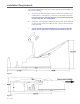
Installation Requirements To install the Winegard Pinnacle® RV Satellite System, Model RD-9946, you will need the following: Figure 1 Figure 2 4 Rev 9/98 A. An area on the RV/coach large enough to allow free movement of the antenna/mount. See Figures 1, 2 and 3 for mount/antenna clearance. If you do not have an area large enough, you can build up the mount so that it will clear ALL obstructions. B. A roof plan of your RV/coach showing the rib locations.
Figure 4 Rev 9/98 5
Installation NOTE: If your RV/coach has been prewired for the Winegard Pinnacle RV Satellite System, RD-9946 proceed to step 2. 1. Your RV/coach design (i.e. flat roof, rounded roof, obstructions, etc.) will determine how and where you mount the system.
Seal connections from point to point indicated Use FS-8100 connector to connect coax cables Figure 7 5. Set mount assy. onto the mount base, making sure to coil cables under mount base. Make cables do not make contact with the azmuth limit switches on the bottom of the mount assembly, Figure 9. Rotate mount assembly. counterclockwise to lock mount onto mount base. Secure mount assy. to mount base using screws provided. See Figure 8. Mount Assembly Set mount assy.
Azmuth Spring Azmuth Limit Switches During installation make sure these cables DO NOT come into contact with the azmuth spring of limit switches.
6. Attach coax cable from antenna assy. to jack on mount, see Figure 10. Make sure to feed coax cable under the shaft. Slide weather boot over boot collar. 7. Attach antenna/feed assembly to mount with (2) 10-32 x 1-1/8" screws and washers provided, see Figure 10. (Torque: 6 ft. lbs.) Antenna/Feed Assembly (2) 10-32 x 1/1/8" Hex Head Screw (2) 10-32 Washers Mount Assembly Figure 10 Feed coax under shaft. Rev.
8. After feeding cable to where you are going to install the positioner, strip 3/8" insulation off all wires in the 13 cable bundle. 9. Attach wires as shown in Figure 11 to the 13 pin connector supplied. Double check that wires will not pull out and that wire colors are correct. NOTE: The first color is the primary color of the wire. Example; Red/ White, means that the wire is red with a white stripe. 13 Pin Connector Green/Black Screws used to secure connector to positioner.
IGN Optional RD-9911 Warning Device Refer to Figure 15, Page 14 for operation and installation. WARNING INDICATOR Connect to ignition +12 VDC. Connect to vehicle ground. After all other connections are made connect AC power cord to 120 VAC outlet. Figure 12 This connection is optional. If used antenna will be put into travel position whenever the ignition is turned ON and there is AC power to the positioner. GOLD SILVER Make sure switch is in the 46CM position. Switch removed 2/23/98.
SENSAR® TV ANTENNA RECEIVER Antenna In POSITIONER Satellite In To Receiver Control Wires To Antenna CH 3/4 OUT TV SET VCR Figure 13 Rev.
NOTE: All commands will be shown in bold with brackets, example [SELECT A]. 11. Plug positioner into AC receptacle. 12. Press [UP/DOWN] arrow until you get Park displayed on positioner display. See Figure 14. 1. Press UP/DOWN arrow buttons to get Park on screen 2. Press SELECT A or B as appropriate SELECT A SELECT B PINNACLE Park Move to Last Sat Model RD-9900 POSITIONER by WINEGARD Figure 14 13. Press [SELECT A or B] Park to put antenna into park (travel) position. See Figure 14.
RD-9901 Remote Control Wall Plate Installation To install the optional RD-9901, proceed as follows: 1. Connect the 25' telephone cord to the REMOTE CONTROL PANEL plug on rear of positioner. See Figure 16. NOTE: The RD-9901 will fit into a standard electrical outlet box. 2. Connect other end of telephone cord to plug on side of RD-9901. See Figure 16. 3. Secure RD-9901 with screws provided. NOTE: Refer to Operation Manual on how to operate the RD-9901.
RD-9911 Warning Device Installation/Operation To install the Warning Device, proceed as follows: 1. Connect the gold colored wire of the warning device wire harness to ignition +12 VDC (there is only +12 VDC present when ignition is turned ON) See Figure 17. 2. Connect the silver colored wire to vehicle ground. See Figure 17. 3. Connect other end of wire (end with molded plug) to warning device. See Figure 17. 4. Insert the two "AA" batteries into the warning device. 5.
Cable Roof-thru Plate Installation If your going to use option B for you cable entry in to your RV/coach proceed to step 1. 1. To install the cable roof-thru plate make sure that you have the following: QTY 1 1 10 Description Part # 3 oz. Silicone Sealant 2460007 Dual cable roof-thru plate 3200159 #10 x 1" Screw 2160178 Use Used to seal cable entry plates Seal dual cable entry Attach cable entry plate(s) to roof 3. Apply silicone sealant under lip of roof-thru plate and where cable enters roof.
MUST PERFORM! READ BEFORE PROCEEDING WITH SYSTEM INSTALLATION OR OPERATION RECEIVER & POSITIONER When plugged in, the receiver & positioner are ON. When connecting or disconnecting any cables to receiver, positioner, or antenna, be sure to unplug from power source. Do not install the receiver and/or positioner where there is no ventilation. The receiver/positioner must have adequate ventilation. Excessive heat can cause premature failure of components.
WINEGARD SERVICE DEPARTMENT (800) 788-4417 S:\PART-NO\2451171A.PM5 After positioner reinstallation, you must put the antenna in the park (travel) position. THIS MUST BE DONE EVEN IF THE ANTENNA IS ALREADY IN THE TRAVEL POSITION. This is done so the positioner will know the antenna position. If not done, damage to the antenna may occur and the system will not operate properly. To park the antenna, refer to Operation Manual. READ BEFORE PROCEEDING WITH POSITIONER REINSTALLATION.
LOCATING THE SATELLITE SUGGESTIONS FOR AVOIDING SATELLITE SIGNAL ACQUISITION ERRORS With the addition of several new U.S. satellites, your system may encounter some difficulty locating the correct satellite on the first attempt. To reduce searching errors, it is recommended that you use the "ENTER ELEVATION" Search method on the Winegard Automatic Positioner. Refer to Pg. 9 in the Operation section of this manual. Elevation can be acquired by entering your local ZIP code in the Receiver Set-up Menu.
WINEGARD ® Pinnacle RV Digital Satellite System Models RD-9946 ® Operation Manual U.S. Patent No. 5,532,710 WARNING! BEFORE ATTACHING OR REMOVING ANY CABLE/WIRES ON BACK OF POSITIONER, UNPLUG UNIT FROM 117 VAC SOURCE. Printed in U.S.A. Winegard Company • 3000 Kirkwood St. • Burlington, IA 52601-2000 • 319/754-0600 © 1998 Winegard Company 2451172 Rev.
IMPORTANT SAFEGUARDS WARNING: THIS SYSTEM HAS BEEN ADJUSTED AT THE FACTORY FOR OPTIMUM PERFORMANCE. BEFORE MAKING ANY ADJUSTMENTS, CONTACT WINEGARD CUSTOMER SERVICE. WARNING: TO REDUCE RISK OF FIRE OR ELECTRICAL SHOCK, DO NOT EXPOSE TO RAIN OR MOISTURE. (Not applicable to mount and antenna) Dangerous voltage inside enclosure CAUTION RISK OF ELECTRIC SHOCK DO NOT OPEN Refer to operating, maintenance and safeguard literature accompanying unit.
TABLE OF CONTENTS Introduction ...................................................................................................................................................... 4 System Operation (Finding the digital satellite system satellite(s) ................................................................. 5 Using the City Menu ............................................................................................................................ 5 Entering Elevation Angle ....................
INTRODUCTION / HOW DOES DIGITAL SATELLITE TV WORK? INTRODUCTION Welcome to a new era in RV Satellite reception. A combination of the latest computer and microprocessor technology makes the Winegard Pinnacle® satellite positioner and your digital satellite system receiver the easiest to operate. A simple button stroke will automatically direct the antenna to the satellite. HOW DOES DIGITAL SATELLITE SYSTEM TV WORK? Satellite programming originates from an “uplink” facility.
SYSTEM OPERATION (FINDING THE SATELLITE(S) Your new Winegard RV Digital Satellite System is an easy-to-install, easy-touse satellite TV reception system. Because it mounts on the top of your recreational vehicle, it goes where you go and provides quality reception of digital satellite signal in the continental United States only. NOTE: All commands will be shown in bold with brackets, example [SELECT A]. One requirement must be met to fully enjoy automatic system TV viewing. The RV must be reasonably level.
6. Press [UP/DOWN] arrow buttons to scroll cities, Figure 3. The cities are listed alphabetically by state. Pressing the [RIGHT] arrow button will scroll the list to the first entry of the next state. Pressing the [LEFT] arrow button will scroll the list to the last entry of the previous state. 5. Press SELECT A or B for the nearest city 4.
Positioner is setting appropriate detector level (amount of signal required) SELECT A SELECT B PINNACLE Setting Detector Model RD-9900 POSITIONER by WINEGARD Figure 6 Positioner is moving antenna to start position SELECT A SELECT B PINNACLE Moving to Start Model RD-9900 POSITIONER by WINEGARD Figure 7 System is now searching for satellite SELECT A SELECT B PINNACLE Searching (350) Level = 238 Model RD-9900 POSITIONER by WINEGARD Figure 8 System has found the satellite and is fine tuning
System has found a satellite and is fine tuning the signal SELECT A SELECT B PINNACLE Fine Tuning Elevation Model RD-9900 POSITIONER by WINEGARD Figure 10 9. Verify that system has found correct satellite (you will see a picture). Since DBS services use a digital signal and the satellites are only separated by 9o, the system can find the wrong satellite. Press [SELECT A] if correct satellite was found, Figure 11.
Finding the Satellite Method 2: Entering the Elevation One requirement must be met to fully enjoy automatic system TV viewing. The RV must be reasonably level. Any of the leveling indicators available should be adequate for this purpose. If the RV is not leveled, the system may not find the high power satellites. After the RV has been leveled, proceed as follows: To find the satellite by entering the elevation angle for your location, proceed as follows: 1.
5. Press [ARROW BUTTONS] to enter correct elevation, Figure 14. 4. Press UP arrow button to increase elevation by 1 o increments 5. Press SELECT A 4. Press RIGHT arrow button to increase elevation by 5o increments SELECT A SELECT B PINNACLE El Angle = 45 Model RD-9900 POSITIONER by WINEGARD 4. Press LEFT arrow button to decrease elevation by 5o increments Figure 14 4. Press DOWN arrow button to decrease elevation by 1o increments 6. Press [SELECT A] Start Search, Figure 15.
Finding the Satellite Method 3: Entering the Latitude and Longitude One requirement must be met to fully enjoy automatic system TV viewing. The RV must be reasonably level. Any of the leveling indicators available should be adequate for this purpose. If the RV is not leveled, the system may not find the high power satellites.
7. Press [ARROW BUTTONS] to display correct latitude, Figure 19. 6. Press SELECT A 5. Press UP arrow button to increase latitude by 0.1o increments 5. Press RIGHT arrow button to increase latitude by 1o increments SELECT A SELECT B PINNACLE Latitude = 40.8 Model RD-9900 POSITIONER by WINEGARD 5. Press LEFT arrow button to decrease latitude by 1o increments Figure 19 5. Press DOWN arrow button to decrease latitude by 0.1o increments 8. Press [SELECT A] to enter latitude, Figure 19. 9.
11. Press [SELECT A] Start Search, Figure 21. This will begin the search for the satellite. If you entered the wrong latitude/longitude, press [SELECT B] Quit, this will return you to step 3. Repeat 3 through 10 to enter the correct latitude and longitude. 9. Press SELECT A SELECT A SELECT B PINNACLE Start Search Quit Model RD-9900 POSITIONER by WINEGARD Figure 21 12. Verify that system has found correct satellite (you will get a picture).
PUTTING ANTENNA IN PARK POSITION NOTE: All commands will be shown in bold with brackets, example [SELECT A]. To put antenna in park (travel) position, proceed as follows: 1. Press [UP/DOWN] arrow until you get Park displayed on positioner display. See Figure 23. 1. Press UP/DOWN arrow buttons to get Park on screen 2. Press SELECT A or B as appropriate SELECT A SELECT B PINNACLE Park Move to Last Sat Model RD-9900 POSITIONER by WINEGARD Figure 23 2.
MOVE TO LAST SATELLITE NOTE: All commands will be shown in bold with brackets, example [SELECT A]. Move to Last Satellite: This function allows you to move the antenna to the last position that the system found a satellite. This feature is very useful. It allows you to put the antenna into the travel position and if the RV/coach was not moved return to watching TV without performing the search function. To move antenna to the last satellite position, proceed as follows: 1.
MANUAL MOVEMENT NOTE: All commands will be shown in bold with brackets, example [SELECT A]. Manual Movement: This function allows you to manually move the antenna. This feature is not normally used. Since the satellite signals are digital, once the system acquires the signal, you cannot improve the picture, only increase the signal strength. To manually move the antenna, proceed as follows: NOTE: To manually lower the antenna to the travel position, refer to the Troubleshooting Manual. 1.
Azimuth Stop Condition (see note) Azimuth Count - Numbers changed according to antenna position Az(X) = XXXXX El (X) = XXXXX Elevation Stop Condition (see note) XXX Signal Level - This will vary according to received signal Azimuth Count - Numbers changed according to antenna position Figure 28 NOTE: There are five (5) motor stop conditions: 0 - Motor stopped under normal conditions. 1 - Motor stopped because a limit switch was encountered. 2 - Motor stopped because motor count limit was reached.
EDIT MENU NOTE: All commands will be shown in bold with brackets, example [SELECT A]. This Edit Menu allows you edit/perform the following functions: Select and edit the search satellite, return system to factory defaults, access the test functions menu, and display the system type and software version. To access the Edit Menu, proceed as follows: 1. Press [UP/DOWN] arrow until Edit is displayed on positioner. See Figure 29. 2. Press [SELECT A or B] Edit, see Figure 29. 1.
Select Search Satellite The Select Search Satellite allows you to perform the following: Select which DBS satellite the system will search for, or edit the satellite name and position. To change the search satellite, proceed as follows: 1. Press [SELECT A] Select Search Sat, see Figure 31. 1. Press SELECT A SELECT A SELECT B PINNACLE Select Search Sat Set Motor Positions Model RD-9900 POSITIONER by WINEGARD Figure 31 2.
Add/Edit Search Satellite If you cannot find the search satellite you want, you must add it to the positioner memory. To add/change the search satellite proceed as follows: 1. Perform steps 1 through 4 page 18 if you are not in the Edit Menu. 2. 1. Press SELECT A Press [SELECT A] Select Search Sat, see Figure 34. SELECT A Select Search Sat Set Motor Positions SELECT B PINNACLE Model RD-9900 POSITIONER by WINEGARD Figure 34 2.
5. After entering satellite name, you must enter satellite location. This is usually expressed in so many degrees west (ex. the DSS satellites are located at 101o west). Your receiver manual or program provider should tell you the satellite position. To enter satellite position, press [RIGHT] arrow key until satellite name is no longer highlighted, see Figure 37. Press [UP/DOWN] arrow keys to scroll to correct number. Numbers will scroll in .5o increments. If satellite location is XX.3, scroll number to XX.
Set Motor Positions Set Motor Positions is only used to lower antenna if limit switches have failed. Refer to troubleshooting section on how this procedure is performed. Test Functions Test functions is used to test various components of the system, refer to troubleshooting section on use. Return to Defaults Return to Defaults is used to return the positioner to factory settings. This should only be done when instructed to do so by a qualified technician. Refer to troubleshooting section on use.
REMOTE PANEL OPERATION NOTE: All commands will be shown in bold with brackets, example [SELECT A]. The Remote Panel allows you to "hide" the positioner and still operate the system from the remote panel. Figure 39 shows the remote panel controls and operations. NOTE: Remote Control Panel will not work if the positioner is performing/ accessing any menu. Example: City menu, Manual Movement, Edit Menu, etc.
Parking the Antenna To park the antenna from the remote control panel, press [PARK] button. See Figure 39. Both LED's will light while antenna is moving; only the park LED will stay on once the antenna is in the park position. To stop the park function, press [PARK or SEARCH] button. NOTE: Remote Control Panel will not work if the positioner is performing/ accessing any menu.
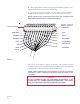
45o 50o 55o 65 65o 60o 50o 55o 30o 35o 40o 45o 25o 125o 120o 115o 110o 105o 100o 95o 90o 85o 80o 75o 70o 65o NOTE: The closer you estimate your latitude and longitude the more accurate the system will be. Before using this map try a local airport or city engineer; they should have the correct latitude & longitude for your location.
15 WARNING INDICATOR IGN 14 13 46 CM 60CM POSITIONER by WINEGARD PINNACLE SELECT B SELECT A 2 12 Figure 41 WINEGARD P/N:2750255 117 VAC 60Hz 100 WATTS MAX REMOTE CONTROL PANEL 3 1 GREEN/BLACK 11 4 5 10 10 BLACK/WHITE 7 ORANGE 1 13 BLUE/BLACK 12 WHITE/BLACK 11 ORANGE/BLACK 9 WHITE 8 BLUE 6 BLACK 5 RED 4 GREEN 3 RED/WHITE 2 RED/BLACK 8 TO ANTENNA TO RECEIVER 7 9 Model RD-9900 6
POSITIONER CONTROLS & INDICATORS POSITIONER CONTROLS & INDICATORS Positioner front and back panel wiring and controls. See Figure 41. The call-outs explain panel controls, indicators and wire connections. If you need information on system installation, refer to the Installation Manual. 1. SELECT A: Selects command/option displayed on top line of display. 2. SELECT B: Selects command/option displayed on bottom line of display. 8. TO RECEIVER: 75 ohm connection to satellite receiver.
NOTE: The system will work in areas not covered by the programmed cities. You can enter the elevation (the DBS receiver will give the correct elevation) or the latitude and longitude of your location.
SPECIFICATIONS / WARRANTY Positioner Specifications Antenna Specifications RF Input Frequency ....................... 950-1450 MHz Input Impedance ....................... 75 ohms Reflector Diameter: ......................... 46 cm (18") Gain at mid-range: 11.2 GHz ...................................... 33.22 dBi 12.1 GHz ...................................... 33.89 dBi 12.6 GHz ...................................... 34.23 dBi Effective aperture ............................ 46cm Aperture efficiency ......
WINEGARD ® Pinnacle RV Digital Satellite System Models RD-9946 ® Troubleshooting Manual U.S. Patent No. 5,532,710 WARNING! BEFORE ATTACHING OR REMOVING ANY CABLE/WIRES ON BACK OF POSITIONER, UNPLUG UNIT FROM 117 VAC SOURCE. Printed in U.S.A. Winegard Company • 3000 Kirkwood St. • Burlington, IA 52601-2000 • 319/754-0600 © 1999 Winegard Company 2451172 Rev.
IMPORTANT SAFEGUARDS WARNING: THIS SYSTEM HAS BEEN ADJUSTED AT THE FACTORY FOR OPTIMUM PERFORMANCE. BEFORE MAKING ANY ADJUSTMENTS, CONTACT WINEGARD CUSTOMER SERVICE. WARNING: TO REDUCE RISK OF FIRE OR ELECTRICAL SHOCK, DO NOT EXPOSE TO RAIN OR MOISTURE. (Not applicable to mount and antenna) Dangerous voltage inside enclosure CAUTION RISK OF ELECTRIC SHOCK DO NOT OPEN Refer to operating, maintenance and safeguard literature accompanying unit.
Table of Contents No Satellite Found ........................................................................................................................................... 4 Return To Defaults ........................................................................................................................................... 6 Positioner Does Not Respond .........................................................................................................................
No Satellite Found If the system will not find a satellite, perform ALL off the following: 1. Is the receiver is plugged in and turned on? 2. Do you have the correct location entered (city, elevation or longitude/ latitude)? 3. Is the correct search satellite entered? Echostar or DSS should appear behind "Search" on display. 4. Verify that your RV/coach is reasonably level. If the mount is sitting at too much of an angle, the system may be looking too high or too low in the sky to see the satellite. 5.
6. If search satellite and search method is correct (correct city, elevation, etc.) return the positioner to factory default. See Return To Defaults, page 6. If after returning the positioner to factory defaults and reentering the correct city and satellite the system still does not find the satellite proceed to the next step. You will need a voltmeter or Winegard Model TE-1400 voltage tester for steps 7 through 10. 7. Check for +12 to +19 VDC at LNBF coax connector, see Figure 2.
Return To Defaults Perform the following commands to return the positioner to factory defaults: 1. Press [UP/DOWN] arrow until Edit is displayed on positioner. See Figure 3. 2. Press [SELECT A or B] Edit, see Figure 3. 1. Press UP/DOWN arrow buttons to get Edit on screen 2. Press SELECT A or B as appropriate SELECT A SELECT B PINNACLE Edit Search DSS Model RD-9900 POSITIONER by WINEGARD Figure 3 3. Press [UP] arrow button until positioner display shows 3000. See Figure 4. 4.
5. Press [UP/DOWN] arrow until Return to Defaults is displayed on positioner. See Figure 5. 6. Press [SELECT A or B] Return to Defaults, see Figure 5. 6. Press SELECT A or B as appropriate 5. Press UP/DOWN arrow buttons to get Return to Defaults on screen SELECT A SELECT B PINNACLE Test Functions Return to Defaults Model RD-9900 POSITIONER by WINEGARD Figure 5 7. Press [SELECT A] Set to Defaults. See Figure 6. 7.
Positioner Does Not Respond If the positioner does not respond to commands, proceed as follows: 1. Unplug positioner from AC power for 3 seconds, then plug positioner back into AC power. The positioner will display the normal menu. See Figure 8. 1. Press SELECT B Park Name of search satellite SELECT A SELECT B PINNACLE Search Park XXXXXX Model RD-9900 POSITIONER by WINEGARD Figure 8 2. Press [SELECT B] Park to put antenna into the park position. See Fig. 8. 3.
Test RD-9901 Remote Control Wallplate To check the Remote Control Wall Plate, proceed as follows: 1. Check that telephone-type cable is plugged securely into jack on positioner rear panel. 2. Check that telephone type cable is plugged securely into jack on side on remote control wall plate. 3. Access Edit Menu; press [UP/DOWN] arrow buttons until Edit is displayed on positioner display. See Figure 9. 4. Press [SELECT A or B] as appropriate to enter Edit Menu. See Fig. 9. 1.
5. Press SELECT B Test Remote Panel SELECT A SELECT B PINNACLE Test LNB Test Remote Panel Model RD-9900 POSITIONER by WINEGARD Figure 11 8. Press [SELECT A] Test Remote Panel, see Figure 12. The positioner will read the elevation from the remote panel. See Figure 13; verify that elevation is same as on remote panel. 6.
7. Press [SELECT B] to return to just Test Remote Panel being displayed, see Figure 14. 7. Press SELECT B SELECT A SELECT B PINNACLE Test Remote Panel Model RD-9900 POSITIONER by WINEGARD Figure 14 8. Press [UP] arrow button twice. Search LED will light on remote panel when Search LED = On is displayed on positioner. See Figure 15. 8. Press UP arrow button twice SELECT A SELECT B PINNACLE Test Remote Panel Search LED = On Model RD-9900 POSITIONER by WINEGARD Figure 15 9.
10. Press [RIGHT] arrow button twice. Park LED will light on remote panel when Park LED = On is displayed on positioner. See Figure 17. 10. Press RIGHT arrow button twice SELECT A SELECT B PINNACLE Test Remote Panel Park LED = On Model RD-9900 POSITIONER by WINEGARD Figure 17 11. Press [LEFT] arrow button twice. Park LED will extinguish on remote panel when Park LED = Off is displayed on positioner. See Figure 18. 11.
13. Press [PARK] button twice. Park Key Pressed will be displayed on positioner. See Figure 20. SELECT A SELECT B PINNACLE Test Remote Panel Park Key Pressed Model RD-9900 POSITIONER by WINEGARD Figure 20 If any of the preceeding tests failed, check cable going from the remote panel to the positioner for cuts, abrasions, etc. If cable is defective, replace with 6-wire telephone type cable. If remote still does not work, contact Winegard Service Dept. To exit test remote panel, press [SELECT B] twice.
Test LNB To test the LNB, proceed as follows: 1. Turn receiver ON. Make sure antenna is not pointed at a satellite (no picture or signal). 2. Access Edit Menu, press [UP/DOWN] arrow buttons until Edit is displayed on positioner display. See Figure 21. 3. Press [SELECT A or B] as appropriate to enter Edit Menu. See Figure 21. 1. Press UP/DOWN arrow buttons to get Manual Move on screen 2.
6. Press [SELECT A] Test LNB, see Figure 23. The positioner will display the menu shown by Figure 24. 5. Press SELECT A Test LNB SELECT A SELECT B PINNACLE Test LNB Test Remote Panel Model RD-9900 POSITIONER by WINEGARD Figure 23 Pressing the UP arrow button will increase attenuation by +4 dB Antenna attenuation level, this will vary from 0 to 28 dB SELECT A SELECT B PINNACLE Antenna = 0 dB Level = 954 Model RD-9900 POSITIONER by WINEGARD Figure 24 Signal level, max. is 1024 min.
Positioner Does Not Come On If the positioner does not come on, proceed as follows: 1. Verify that the 46 CM - 60 CM switch (on the back panel) is all the way to the left or right. If switch is in the middle, positioner may not turn on. See Figure 25. WARNING INDICATOR WINEGARD P/N:2750225 120 VAC 60Hz 100 WATTS MAX IGN REMOTE CONTROL PANEL 46 CM 60CM Figure 25 Make sure switch is all the way left or right depending on whether your antenna is 46 cm (18") or 60 cm (24"). 2.
Parking System, Fail - Please Check 1. If the positioner displays the message shown in Figure 26, step out of your coach/RV and check the position of the antenna. Press either SELECT A or B SELECT A SELECT B PINNACLE Parking System Fail - Please Check Model RD-9900 POSITIONER by WINEGARD Figure 26 2. If the antenna is not in the travel position, you should climb up and verify that there are no obstructions blocking the antenna.
When Searching Positioner Displays "Search Stopped" If the antenna will not move, check the following. 1. If you have been in an ice storm or freezing rain the mount may be frozen in place. Before checking any of the following steps visually inspect the mount. 2. Double check wiring at the back of positioner. Make sure wires have good contact with the connector plug. 3. Park system and then go to manual movement. Use UP arrow button to move to antenna up.
WINEGARD ® Pinnacle RV Digital Satellite System Models RD-9946 ® Parts List U.S. Patent No. 5,532,710 WARNING! BEFORE ATTACHING OR REMOVING ANY CABLE/WIRES ON BACK OF POSITIONER, UNPLUG UNIT FROM 117 VAC SOURCE. Printed in U.S.A. Winegard Company • 3000 Kirkwood St.
TABLE OF CONTENTS Antenna Support .............................................................................................................................................. 3 Mount Assembly .............................................................................................................................................. 4 Mount Base ......................................................................................................................................................
ANTENNA SUPPORT ASSEMBLY INDEX NO. 1 2 PART NUMBER 2762830 2200945 2240021 DESCRIPTION Antenna Support Assembly Antenna Support, White Antenna Support Bumper, White QTY 1 1 2 Rev.
MOUNT ASSEMBLY Rev.
MOUNT ASSEMBLY INDEX NO.
MOUNT BASE INDEX NO. 1 2 Rev.
POSITIONER/ACCESSORIES 1 2 3 SELECT A SELECT B PINNACLE Model RD-9900 POSITIONER by WINEGARD 4 INDEX NO. 1 2 3 4 * ** PART NUMBER RD-9901 RD-9911 2750225 2753254 DESCRIPTION Remote Control Wall Plate Warning Device Positioner Ignition Wire Harness QTY * ** 1 1 Optional, comes with 25' 6-wire telephone type cord to connect to receiver. Optional, comes with batteries and cables to connect to receiver and vehicle ignition.
ANTENNA/FEED ASSEMBLY Rev.
ANTENNA/FEED ASSEMBLY INDEX NO.
NOTES: 1. 14 wire/coax cable to be jacketed together. 2. Jacket strip length 13 wire cable: 3.00 +.25 both ends. 3. Wire strip length 13 wire cable: .25 +.031 both ends. 35' CABLE, PART NUMBER 2753248 Rev.
MOUNT WIRE HARNESS, PART NUMBER 2753245 For antenna mounts with a serial # of 10111 or higher.