INSTALLATION/OPERATION MANUAL WINEGARD AUTOMATIC RV DIGITAL SATELLITE SYSTEM Model RM-9946 & RM-9947 ® U.S. PATENT NO. 5,532,710 Made in U.S.A. FOR SLOPED ROOFS: Use Winegard’s RW-5000 roof wedge. FOR MULTIPLE RECEIVER INSTALLATIONS: Dual LNBF is required, see page 16. Winegard Company • 3000 Kirkwood St. • Burlington, IA 52601-2000 319/754-0600 • FAX 319/754-0787 • www.winegard.com Printed in U.S.A.
IMPORTANT SAFEGUARDS WARNING: TO REDUCE RISK OF FIRE OR ELECTRICAL SHOCK, DO NOT EXPOSE TO RAIN OR MOISTURE. (Not applicable to mount and antenna) Dangerous voltage inside enclosure CAUTION RISK OF ELECTRIC SHOCK DO NOT OPEN Refer to operating, maintenance and safeguard literature accompanying unit. CAUTION: TO REDUCE RISK OF ELECTRICAL SHOCK, DO NOT REMOVE COVER, NO USER-SERVICEABLE PARTS INSIDE. REFER SERVICING TO QUALIFIED PERSONNEL 1.
Table of Contents OPERATION Introduction ...................................................................................................................................................... 4 Wallplate Control Panel ................................................................................................................................... 5 Automatic Operation ........................................................................................................................................
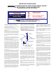
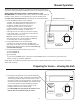
Introduction/How Does Digital Satellite TV Work? Introduction For Programming information call: DISH NETWORKTM - 1-800-333-DISH (1-800-333-3474) DIRECTV® - 1-800-DIRECTV (1-800-347-3288) ExpressVu - 1-888-SKYDISH (1-888-759-3474) Congratulations! You have an RV automated digital satellite reception product — RM-9946. This system, used with your digital satellite receiver, will deliver the best reception possible.
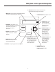
Wall plate control panel description 12. RED LED: Shows Antenna elevated from stow position (any degree from stow). 1. DISPLAY: LCD (Liquid Crystal Display) shows instructions and warnings to operator. 11. GREEN LED: Shows Power is on. ANTENNA POWER 2. POWER: Turns system on or off when pressed. To turn On, hold down one second; to turn Off, hold down 2 seconds. 3. STOW: Places dish in a ready-to-travel, or stowed, position. Power Stow Enter Manual 4.
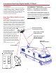
Automatic System Operation After parking and leveling vehicle, look for trees, buildings, hills or mountains that might block the satellite signal. ABOUT YOUR RECEIVER: If you have a DISH NetworkTM receiver, be sure your system (RM-9946) is set to receive DISH Network satellites. If you have a DIRECTV® receiver, be sure your system (RM-9946) is set to receive DIRECTV satellites. (The majority of programming for DISH Network is on satellite 119°W; for DIRECTV it is on 101°W.
Automatic System Operation DON’T UNDERSTAND A MENU? If you see a menu in the display you do not understand, press POWER for two seconds to exit that menu. NOTE 1: The system can move directly to any of the available satellites, if you have a clear view, after the initial search routine at a location. The display will show the message “Pick a sat < > ”. It remains for several minutes after search is complete. To get back to menu, after power has shut off, press POWER.
Manual Operation At any time during any operation, the system may be put in manual control operation mode by pressing the MANUAL button on the wall plate controller. WHEN USING THE MANUAL MODE, THE SYSTEM WILL LOSE INFORMATION. You will not be able to move directly to a satellite without repeating a search process, or automatically go to the last satellite used. Wall Plate Controller To regain these automatic features, follow directions in number 3 below. 1.
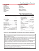
Parts/Specifications/Warranty Tools needed for installation Parts included Level Tape measure Phillips screwdriver Electrical tape Cutter Electric or cordless drill 1/8” drill bit (for pilot holes) 7/16” wrench (for dish assembly) 5/16” socket/nut driver 1-1/2” hole saw (cable entry hole) Sealant compatible with roof material (check with your vehicle manufacturer for compatibility) 18 “Reflector Backup structure Mount base/turret Mount cover & bracket Vent tube Cable entry plate Hardware Cable Interior w
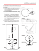
Installation requirements To install the Winegard Automatic Digital Satellite Dish, check with your RV dealer or manufacturer. Your RV may already be pre-wired for this system, and/or may have a reinforced roof area available. FIGURE 1 1. Choose a location on the roof that will allow the dish to raise and rotate without interference from other roof-mounted equipment. 2. Roof space required for operation is 40”L x 20”W minimum. Refer to Figures 1, 2, 3 and 5 for operating parameters. 3.
Mounting motorized dish assembly on roof 1. Position the roof template on the vehicle roof and drill 1/8” holes for the screws. DO NOT drill clear through into interior of vehicle. The screws fasten mount to the roof only. Be sure the roof can securely hold system. 2. Place base plate gasket under the base before screwing unit down. Secure the base plate of the motorized assembly to the roof using appropriate screws. DO NOT APPLY SEALANT AT THIS TIME.
FIGURE 6 First cable clamp here! 4” MINIMUM from first clamp to cable-entry plate The length of this cable MUST BE 53 inches from back of electronics housing to clamp.
5. Cut the cable wrap approximately four (4) inches away from point where it enters the cable-entry plate, Figure 7, 7A. This allows proper sealant coverage. Do not damage cables when cutting away the cable wrap. (The cable wrap protects and keeps together in one unit the coaxial cable, electrical cable and 8 wire data cable.) After cutting, wrap the outer cable wrap with electrical tape as shown, Figure 7, 7A. Push cable through cable entry point on roof. Do not damage cable.
Mounting interior wall plate controller Inside your vehicle, choose a convenient location for the wall plate controller. Consider wiring layout, ease of viewing the information on the readout and distance from your television set. The wall plate uses only 8-conductor cable. Power goes to unit on roof. 1. Install the 8-conductor RJ-45 type cable to the back of the wall plate controller before mounting, Figure 11. 2.
Wiring Wiring the system: This unit requires a +12 VDC fused circuit. Unit draws up to 3 amps. The unit uses sophisticated microprocessor technology and needs “clean” (filtered) power to function properly. DO NOT USE power designated to operate a +12 VDC lighting circuit from the converter, or a converter that does not have a battery connected to it, or any unfiltered converter! Damage to the system could result! If in doubt, contact your dealer or the manufacturer of your vehicle. 1.
Antenna 46 cm Reflector, White P.N. 2745282 (4) Flat Head Bolts (White) P.N. 2160362 LB-1000: STANDARD SINGLE LNBF LB-2000: OPTIONAL DUAL LNBF * Carriage Bolt P.N. 2160353 Flange Nut 1/4-20 (not shown) P.N. 2160228 Roller Backup Frame P.N. 2200460 P.N. 2744939 Hex Head Bolt 1/4-20 xx 2.5" Pivot Bracket Feed Arm P.N. 2160237 P.N. 2744946 Nylock Nut P.N. 2744945 14 - 20 Screw #10-24 x 3/4 (4) Pin, 1/4 x 3.375" long P.N 2160813 P.N. 2160196 (Not shown: E-clip for 1/4" Pin Vent Tube P.N.
Base Assembly Worm Gear Plug P.N. 3200045 O Ring P.N. 2240029 Worm/Shaft Assembly P.N. 2754099 Spring P.N. 2160818 Spacer P.N. 2160425 Motor Housing P.N. 3200260 Electronics top housing, P.N. 3100675 includes screws, P.N. 2160154 Motor Housing Gasket P.N. 2240054 Electronics bottom housing only (P.N. 3100676) Azimuth Motor P.N. 2665039 Screw (3) P.N. 2160196 Gasket P.N. 2240056 Elevation Motor P.N. 2665038 Seal P.N. 2200852 Seal P.N. 2200852 Pivot Shaft P.N. 2590344 Turret P.N.
Turret Assembly TURRET ASSEMBLY Screw 10-32 x 3/8” (10) P.N. 2160197 Rotate Motor Gear P.N. 2200468 Screw, Motor Housing (4) P.N. 2160195 Idler Gear P.N. 2200467 Wire Clamp (2) P.N. 3720053 Pivot Bushing P.N. 2200470 Elevating Gear P.N. 2200464 Down Limit Switch Bracket (w/o switch) P.N. 3200263 Shoulder Bolt P.N. 2160355 Cover Cover P.N. 2200015 (4) Phillips Head Screw(s) P.N. 2160193 (4) Nylon Screw Receptacle Insert P.N. 2200112 (4) Hex Head Screw(s) P.N. 2160198 Cover Bracket P.N.
Troubleshooting the system ! Some of the problems we are troubleshooting here are marked with this symbol. For these problems, we advise you to seek professional service. Contact the retailer or dealer where you purchased this system, or call Winegard Technical Support at 1/800/-788-4417, Monday through Friday, 7:00 a.m. to 4:00 p.m., Central Time. Solutions to problems in this manual have been categorized according to type.
Troubleshooting tips 1. Check fuse on supply circuit (power source for system). If +12 VDC is present, check the motorized unit on roof. Remove white plastic cover on the mount. Remove electronics housing cover and check the main board, J8 connector, for +12 VDC and ground. If there is voltage present and the cable harness is not damaged, contact Winegard Technical Services at 800/788-4417.