
Operating instructions


3
Table of Contents
OPERATION
Introduction ...................................................................................................................................................... 4
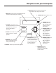
Wallplate Control Panel ................................................................................................................................... 5
Automatic Operation ........................................................................................................................................ 6
Manual Operation ............................................................................................................................................ 8
Stowing Dish .................................................................................................................................................... 8
INSTALLATION
Tools Needed............................................................................................................................................... 3, 9
System Components, Specifications, Warranty Information ........................................................................... 9
Installation Requirements .............................................................................................................................. 10
Mounting Assembly on Roof ..................................................................................................................... 11-12
Mounting Interior Wall plate Controller .......................................................................................................... 14
Wiring... .......................................................................................................................................................... 15
PARTS
Antenna Parts ................................................................................................................................................ 16
Base Assembly .............................................................................................................................................. 17
Turret Assembly/Cover .................................................................................................................................. 18
ADDITIONAL INFORMATION
Troubleshooting ........................................................................................................................................ 19-20
FCC PART 15 STATEMENTS
NOTE: This equipment has been tested and found to comply with the limits for a Class B digital device, pursuant to Part 15
of the FCC Rules. These limits are designed to provide reasonable protection against harmful interference in a residential
installation. This equipment generates, uses and can radiate radio frequency energy and, if not installed and used in accor-
dance with the instructions, may cause harmful interference to radio communication. However, there is no guarantee that
interference will not occur in a particular installation. If this equipment does cause harmful interference to radio or television
reception, which can be determined by turning the equipment off and on, the user is encouraged to try to correct the interfer-
ence by one or more of the following measures:
• Reorient or relocate the receiving antenna.
• Increase the separation between the equipment and receiver.
• Connect the equipment into an outlet on a circuit different from that to which the receiver is connected.
• Consult the dealer or an experienced radio/TV technician for help.
CAUTION: Any changes or modifications to this equipment not expressly approved by Winegard Company may void
the user’s authority to operate this equipment.
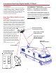
Parts included:
18 “Reflector
Backup structure
Mount base/turret
Mount cover & bracket
Vent tube
Cable entry plate
Hardware
Cable
Interior wall plate controller
Surface mount box
Tools needed for installation:
Level
Tape measure
Phillips screwdriver
Electrical tape
Cutter
Electric or cordless drill
1/8” drill bit (for pilot holes)
7/16” wrench (for dish assembly)
5/16” socket/nut driver
1-1/2” hole saw (cable entry hole)
Sealant compatible with roof material (check
with your vehicle manufacturer for compatibility)