® RV DIGITAL SATELLITE SYSTEM with Digital Elevation Sensor Model RM-DM46 may also be packaged as RM-DM00, RMDM04, RMFLDM4 U.S. Patent Number 5,532,710 Made in U.S.A. Winegard Company • 3000 Kirkwood St. • Burlington, IA 52601-2000 319/754-0600 • FAX 319/754-0787 • www. winegard.com Printed in U.S.A. © Winegard Company 2002, 2005 2451069 Rev.
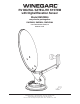
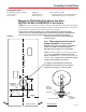
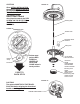
Operation STEP 1. The more accurately you determine North, the easier it is to locate the satellite. Step outside and away from your vehicle. (Standing to near your vehicle can give incorrect compass readings.) It is helpful if there is a landmark on the horizon to represent North. Return to the vehicle and point the Directional Dial North, or to the landmark. DIRECTIONAL HANDLE ELEVATIING CRANK DIRECTIONAL DIAL DIRECTIONAL HANDLE POIINTER FIGURE 1 RED SCREW ROTATION CLAMP STEP 2.
Tuning Antenna STEP 1. Your receiver should indicate it is receiving a signal. To tune your antenna for the best signal strength. SLOWLY move the antenna left, then right, until you have found the position that gives the highest signal strength. It is important to turn the antenna slowly. Because the signal is digital, the receiver takes a few seconds to lock on. STEP 2. Place rotation clamp in the LOCK position. This prevents an tenna movement and loss of signal. STEP 3.
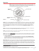
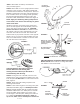
Trouble Shooting Antenna Reflector at 90° Sig na l fr om sa tel 24° look angle LNBF FIGURE 2 lite 1. You may need to roatate the dish in small increments to find the signal. Rotate the dish 3° at a time to the left, stopping for a few seconds each time you move the dish. Try moving the dish up to 20° to the left. If no signal is found, return to the azimuth listed and and try rotating 20° to the right. This will help correct for any errors in setting the directional handle. 2.
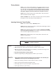
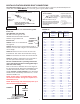
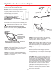
Assembly & Installation Things you need — Screwdrivers (Phillips and slot) 1-3/4” hole saw 7/16” wrench Non-hardening sealant (Check manufacturer’s specifications for compatibility with your roof material.) ABS glue Drill with 1/8” bit Tape measure Winegard’s Digital Elevation Sensor has been INSTALLED and CALIBRATED at the factory STEP 1. Choose a location on the roof for dish that will allow dish to raise and rotate without FIGURE 3 interfering with other roof-mounted equipment.
STEP 3. Attach dish to backup. Use bolts and nuts provided, Figure 4. (4) Antenna Mounting Bolts STEP 4. Mount dish on roof in upright position. Rotate clockwise to stop, Figure 5. Dish will be toward back of vehicle when in stowed or travel position. The word FRONT is embossed on the base and should face the front of vehicle. Secure to roof using screws (provided). The travel bracket sjhould be mounted to roof 6-1/8” from base of dish, toward back of vehicle. See Figure 6.
DIGITAL ELEVATION SENSOR ROOF CONNECTIONS The illustrations below show the different methods of connecting wires at roof level; method will depend on model. Wire colors MUST MATCH, ie. red to red, green to green, black to black. This wire harness connects to the digital elevation sensor on the antenna Snap connectors together Supplied with DM-2000 only 3M UR TERMINAL DO NOT STRIP wires, terminal is self-stripping. Slide wires all the way in.
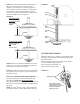
FIGURE 12 STEP 15. The directional handle and threaded rod will fit roofs up to 5-1/4” thick. If you are using wedges to compensate for roof/cceiling slope, be sure to allow for this extra thickness. You may add an extension to the directional handle for thicker roofs. Each extension will increase the length of the directional handle by 2-1/4”. Figure 11 Plastic Plug Spacer Spring FIGURE 11 WITH ROOF WEDGE Measure from top of roof wedge to ceiling.
CAUTION! After INITIAL INSTALLATION, the antenna SHOULD ROTATE APPROXIMATELY 360° FROM TRAVEL POSITION. The pointer on the DIRECTIONAL HANDLE should point towards the RED SCREW ON THE ROTATION CLAMP when in the TRAVEL POSITION. FIGURE 15 Elevating Shaft FIGURE 14 Threaded Tube Directional Handle Extension Ceiling Plate Pointer must point to RED SCREW at CENTER OF ROTATION CLAMP when in travel position.
Digital Elevation Sensor Interior Wallplate STEP 19. See Figure 17. If using the SM-1000 surface mount box, feed cable through hole in box. FIGURE 17 STEP 20. Connect wires coming from sensor on roof to wall plate display in vehicle. It is important to properly connect the wires at the roof and the wall plate. (Plug will click when inserted properly.) The system is designed to use a 9 volt battery OR +12 VDC from vehicle. Do not use both! IMPROPER WIRING WILL CAUSE DAMAGE TO THE PRODUCT, SEE FIGURE 18.
Parts List 11
Parts List 12
Parts Views Rev/6/11/01 13
Notes 14
Notes 15
Specifications ANTENNA & MOUNT Height when raised Height in the travel position Operating radius17" Roof space required LNB Weight Color Antenna height Antenna width F/D Offset angle Frequency range Gain: 11.2 GHz 12.1 GHz 12.6 GHz Aperture efficiency Cross polarization (on axis) *Beamwidth at -3 dB *Beamwidth at -10 dB Wind loading Ship weight: 30" verticle max. 8" max. (34" diameter circle) 26" Compatible with DIRECTV®, DISH NetworkTM , and ExpressVu (northern U.S. and Canada) 12 lbs. Cool gray 20.9" 19.
TEMPLATE ON NEXT PAGE 17
ALIGN BASEP AREA M “FRO POINT TO OF VEH 1-3/4” DIA.
Roof Template WITH PLATE MARKED ONT” O FRONT HICLE 1/8” DRILL BIT 8 HOLES. DO NOT DRILL THROUGH CEILING.