
Installation Manual


2
NOTE: Maintain a minimum of 10" from the edge of the roof or any
obstruction (16" must be maintained if installing a Sensar IV). Check
with your dealer or the manufacturer for information about options
in the roof for mounting the antenna. A reinforced roof area, or a
prewired coax cable, may be available. For sloped/round roofs, use
Winegard Model RW-2000 exterior roof wedge, to level installation. An
interior wedge, IW-5000, is also available.
STEP 2: Using template on our website at http://www.winegard.com/
kbase/upload/sensar_template.pdf drill 1-3/4" hole through roof and
ceiling of vehicle. Be careful not to damage any wiring between roof and
ceiling.
STEP 3: Drill 1/2" hole for cable entry through roof of vehicle only. DO
NOT DRILL THROUGH CEILING. Route cable through ceiling and wall to
power supply location.
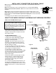
STEP 4: The mount is designed to t roofs from 1" to 4-3/4" thick. As
supplied, the mount will t a roof 4-3/4" thick. If roof is less than 4-3/4"
thick, cut elevating shaft and directional handle to size, steps shown
in gures 2, 3, 4 and 5. If roof is more than 4-3/4" thick (max. 7"), a
directional handle extension is needed. Order Winegard Model
EK-1036, Directional Handle Extension.
IMPORTANT: The handle and extension must be glued together after
checking that you have the correct length. The handle will not work
properly if it is not glued together! (PVC glue is recommended; for your
safety, use according to manufacturer's directions.)
NOTE: If using roof wedge RW-2000 or interior wedge IW-5000, put in
place before installing base plate or interior hardware.
2452013-Installation/Operation
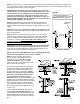
STEP 1: Choose location for antenna. Figure 1 illustrates placement of the Sensar, showing it in travel position.
You must be able to raise and rotate antenna without interfering with other roof-mounted equipment. Make sure
inside ceiling area is clear to mount ceiling plate.
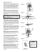
STEP 5: Center elevating shaft in hole on
roof. Temporarily secure base plate to roof
with two screws provided. (Do not apply
sealant at this time). Inside unit, make a
mark on the shaft 1-1/2” below ceiling and cut
shaft on this mark. See gure 2.
After cutting elevating shaft, push directional
handle up into ceiling over shaft being careful
to align keys inside directional handle onto
keyways on bottom of gear housing. (NOTE:
The keys only line up one way; do not force.
TIP: Pointer on directional handle should
point toward back of coach if properly
installed.) Make sure directional handle is snug
against bottom of baseplate. Measure distance
between the bottom of the recess on the handle
to the ceiling. See gure 3. Pull handle back
down and transfer this dimension to the shaft
end of the directional handle. Mark it and cut it
off here, g. 4.
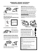
If EK-1036 (directional handle extension) is
used, DO NOT CUT EK-1036 extension. Cut
excess length from directional handle only. The
handle and extension must be glued together
after checking that you have the correct length,
g. 5.
FIGURE 1
10" Minimum
Distance
If installing a Sensar
®
IV, a
minimum distance of 16" must
be maintained from the edge of the
roof and from the nearest obstruction.
10"
10"
10"
To Nearest
Obstruction
10"
2′
2′
10"
FRONT OF VEHICLE