Winegard® Dealer Training TRAV’LER® Antennas 1 Parts 2 Installation 7 Operation 9 Conversion Kits & Troubleshooting 2 2 3 4 6 7 7 7 8 8 8 9 9 9 10 10 10 Warnings Roof Location Requirements Installing the TRAV’LER Mount Base Wiring the TRAV’LER Antenna Sealing Installing the Reflector Basic Operation Receiver Setup Search Modes Raising, Lowering, and Stowing the Antenna Hard Power Off RP-SK21/11 & OE-DISH Calibrate EL Emergency Manual Stow Accessories & Replacement Kits Accessories Replacement Ki
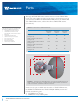
Parts Although all TRAV’LER multi-satellite antennas include a TRAV’LER mount base and a satellite provider specific reflector, the dimensions vary in size between the DIRECTV SWM TRAV’LER antenna, the DISH®/Bell TV™ TRAV’LER antenna, and the Shaw Direct TRAV’LER antenna (see table 2.1).
Installation Warnings Do not attempt to install this system in the rain or under any wet conditions. Moisture may affect electronics and void your warranty. Do not paint the antenna. Painting the antenna will void your warranty. Pay attention to the pinch points as the antenna raises. The pinch points should be labeled on the antenna. Roof Location Requirements Before installing the antenna, make sure that the chosen location meets the minimum roof space requirements for the antenna (see table 2.2).
Installation Roof Location Requirements, Cont. The chosen location on the roof must be within five degrees of level and offer enough support for a secure installation. Do not install the TRAV’LER antenna in a location where a gap of 3/16″ or more exists between the bottom of the antenna and the roof, as the antenna may damage the roof. Finally, choose a location for cables to enter the vehicle. Cables must not be run through the area where the reflector stows.
Installation Wiring the TRAV’LER Antenna Once the base has been properly installed, cables should be connected. Cables should be run with some slack. In order to leave room for service, do not pull cables too tightly. Depending on the length of the cable on the roof, you may need to use cable clamps between the unit and the cable entry plate. Clamping every 12–16″ should eliminate any unnecessary cable movement.
Installation Wiring the TRAV’LER Antenna, Cont. When connecting the DIRECTV SWM TRAV’LER antenna to receiver(s), only port C should be used for making connections to the mount base; multiple receivers will connect to the mount base via the provided splitter. The power inserter must not be mounted on the roof of the vehicle. The power inserter must always be installed inside the vehicle. If hooking up to only one receiver, the splitter is not needed, but the power inserter must still be installed.
Installation Sealing After completing wiring, return to the roof. Seal around the hole where cables enter the vehicle, and seal around the cable entry plate (see fig. 2.5). A B C D FIGURE 2.5. Sealing point of cable entry. A, Positioning cable entry plate over sealed hole. B, Securing cable entry plate to roof. C, Securing cable clamps. D, Sealing. The unit can be removed from the transition plate. See figure 2.7.
Operation Installing the Reflector If it is not possible to install the reflector with the unit in the stowed position, press “POWER” to turn on the unit, and as the antenna raises, press “POWER” and “SELECT” at the same time; when the antenna stops moving, the reflector can then be installed. In most cases, the reflector can be installed with the unit in the stowed position.
Operation Search Modes The TRAV’LER antenna offers a simple one-button automatic operation. In addition to Automatic mode, the interface includes a Manual mode with a user menu for advanced features. Always use Automatic mode for normal operation. The Diagnostics menu should not be entered or used unless advised by Winegard personnel. Raising, Lowering, and Stowing the Antenna The user menu includes options to manually move the dish, including raising, lowering, and stowing the antenna.
Conversion Kits & Troubleshooting During a conversion to a DISH TRAV’LER antenna, the reflector and cable harness have been removed. The coaxial cables are disconnected from the turret. The reflector bracket and stiffener plate have not yet been removed (see fig. 2.10). A B FIGURE 2.10. Reflector, cable harness, and coaxial cables removed and/or disconnected for conversion. A, Reflector bracket. B, Stiffener plate.
Accessories & Replacement Kits Accessories Various accessories are available for the TRAV’LER antenna, including Model CL-SK26 control cable extension, Model SKA-004 roller plate, and Model SKA-008 thin roof plate. Model CL-SK26 is a 25′ power/ communication cable that connects directly to the existing TRAV’LER power cable to allow runs up to 55′. Model SKA-004 is a roller plate for protecting a rubber RV roof.
Winegard Company • 3000 Kirkwood Street • Burlington, IA 52601 • 1-800-288-8094 • Fax 319-754-0787 • www.winegard.com Printed in U.S.A. ©2013 Winegard Company 2/15 Winegard, RoadTrip, Mission, TRAV’LER, Carryout, Pathway and Rayzar are registered trademarks of Winegard Company. DIRECTV is a registered trademark of DIRECTV, LLC. DISH is a registered trademark of DISH Network L.L.C. Bell TV is a trademark of Bell Canada, Inc. Shaw Direct is a trademark of Shaw Satellite G.P.