
Installation manual


9
TRAV’LER Multi-Satellite TV Antennas
Conversion Kits & Troubleshooting
Conversion Kits & Troubleshooting
RP-SK21/11 & OE-DISH
Conversion kits are available for the TRAV’LER antenna. e conversion kits
are compatible with converting the DIRECTV Slimline antenna (SK-3005),
DIRECTV triple LNB (SK-3003), or DIRECTV SWM Slimline antenna
(SK-SWM3) to the DISH TRAV’LER antenna (SK-1000).
To convert from a DIRECTV TRAV’LER antenna to a DISH TRAV’LER
antenna, complete the following steps:
1. If converting a DIRECTV SWM Slimline antenna to a DISH TRAV’LER
antenna, remove the power inserter and SWM splitter; these will not be used.
2. Remove the reector.
3. Disconnect the coaxial cables from the turret, remove the bolt holding the
cable harness to the unit, and detach the cable harness from the lift arm.
4. Remove the reector bracket. If applicable, remove the stiener plate.
5. If applicable, remove the adaptor plate.
6. If applicable, install a new adaptor plate. en, align the four holes on the
inside of the reector bracket with the four holes in the adaptor plate (see
g. 2.11). Replace
3
/
16
″ Allen screws through the four holes, and tighten.
7. Connect and tighten the coax cables. Leave port D open, and install an
F-cap on port D. e F-cap will not be used if converting from a SWM
TRAV’LER antenna.
8. Replace the clamp that holds the coax cables to the arm with a
5
/
16
″ screw.
If the cable tie is missing or was not used to mark the position of the clamp
on the cable harness, install the clamp 14″ from the end of the connectors.
9. Set the IDU for DISH 1000.
10. Repackage the LNB, and return the repackaged parts to Winegard.
Calibrate EL
If the TRAV’LER antenna is stuck in the deployed position, the elevation may
need to be re-calibrated. Select “Calibrate EL” from the Installation menu. After
a few moments, the interface box will display, “On EL hard stop?/Yes No*.” If
the antenna is pointing as far upwards as it can go, then press the Select button
to move the asterisk to “Yes,” and press Enter to conrm the selection. e
antenna should now be able to be stowed. If not, contact Winegard Technical
Services for additional help, or follow the emergency manual stow procedure.
“Restore to factory defaults” is also used when issues occur.
Emergency Manual Stow
Emergency manual stow can be used as a last resort if unable to stow the
antenna otherwise. First, unplug the interface box. en, remove the black
plastic bolt from the back of the mount. Insert a
3
/
8
″ socket extension into the
auxiliary drive, and turn clockwise to lower the unit. Do not use a drill!
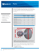
During a conversion to a DISH
TRAV’LER antenna, the reflector and
cable harness have been removed.
The coaxial cables are disconnected
from the turret. The reflector bracket
and stiffener plate have not yet been
removed (see fig. 2.10).
A
B
FIGURE 2.10. Reflector, cable
harness, and coaxial cables
removed and/or disconnected
for conversion. A, Reflector
bracket. B, Stiffener plate.
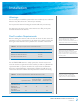
To install the DISH reflector and LNB
assembly, four holes in the reflector
bracket must align with four holes in
the adaptor plate (see fig. 2.11).
1
2
3
4
1
2
3
4
FIGURE 2.11. Four holes to
align in reflector bracket (left)
and adaptor plate (right)