Part List ITEM DESCRIPTION PART QTY ITEM DESCRIPTION PART |Top Panel Drawer Front 7] ops Panel ret 9 | Left Side 7 Ty 1pc | g | Drawer Left Ny Foes “ Panel Sa” Side Panel “ 3 | Right Side ~TN g | Drawer Right NS Panel pe Side Panel apes Bottom 7 os Drawer Back 4 Panel — fc 110 Panel > apes A Wooden 0 Drawer a Sires S Leg apes | 11 Bottom Panel “] P Back 6 Panel STEP Se Lb i i pri Assemble the wooden legs (5) to bottom panel (4) by using Allen head screw (J), tighten with Allen key (K}. 2.
STEP 2 1. Assemble the metal drawer glide (F2) to side panel using screw (E) as shown. STEP 3 i 1. Insert wooden dowel (C) and screw the cam bolt (A) fo the holes on bottom panel (4) as shown. 2. Attach the left side panel (2) and right side panel (3) to the bottom panel (4). 3. Insert the cam lock (B) to the holes on side panel (2 & 3) then rotate clockwise to secure cam bolt in place.
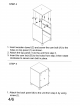
STEP 4 1. Insert wooden dowel (C) and screw the cam bolt (A) to the holes on top panel (1) as shown, 2. Attach the top panel (1) to the unit from step 3. 3. Insert the cam lock (B) to the holes from step 3 then rotate clockwise to secure cam bolt in place. STEP 5 1. Attach the back panel (6) to the unit from step 4 by using screw (1).
1. Assemble drawer side panel (8 & 9) and drawer back panel (10) together by using screw not over tighten, 2. Screw the cam bolt (A) to drawer front panel (7). 3. Assemble the handle (D) to drawer front panel (7) by using screw (E). 4. Assemble the metal rod (G), drawer bottom panel (11) and drawer front panel (7) to the drawer, 5. Insert the cam lock {B) to the holes on drawer side panel {8 & 9) then rotate clockwise to secure cam bolt in place.