Notice to Users ©2003 2Wire, Inc. All rights reserved. This manual in whole or in part, may not be reproduced, translated, or reduced to any machine-readable form without prior written approval. 2WIRE PROVIDES NO WARRANTY WITH REGARD TO THIS MANUAL, THE SOFTWARE, OR OTHER INFORMATION CONTAINED HEREIN AND HEREBY EXPRESSLY DISCLAIMS ANY IMPLIED WARRANTIES OF MERCHANTABILITY OR FITNESS FOR ANY PARTICULAR PURPOSE WITH REGARD TO THIS MANUAL, THE SOFTWARE, OR SUCH OTHER INFORMATION, IN NO EVENT SHALL 2WIRE, INC.
Contents To display the Table of Contents in the left-hand pane, click the Window menu and select Bookmarks. Networking Technology Overview Ethernet . . . . . . . . . . . . . . . . . . . . . . . . . . . . . . . . . . . . . . . . . . . . . . . . . . . . . . . . . . . . . . . . . . . . . . . . . . . . USB . . . . . . . . . . . . . . . . . . . . . . . . . . . . . . . . . . . . . . . . . . . . . . . . . . . . . . . . . . . . . . . . . . . . . . . . . . . . . . . Home Phoneline Networking (HomePNA) . . . . . .
Step 4: Add Computers to the Network Choose a computer and connection type . . . . . . . . . . . . . . . . . . . . . . . . . . . . . . . . . . . . . . . . . . . . . . . . . . Ethernet Connection . . . . . . . . . . . . . . . . . . . . . . . . . . . . . . . . . . . . . . . . . . . . . . . . . . . . . . . . . . . . . USB Connection . . . . . . . . . . . . . . . . . . . . . . . . . . . . . . . . . . . . . . . . . . . . . . . . . . . . . . . . . . . . . . . . . Home Phoneline Networking (HomePNA) Connection . .
Firewall Monitor Setting up Firewall Monitor attack alerts . . . . . . . . . . . . . . . . . . . . . . . . . . . . . . . . . . . . . . . . . . . . . . . . . . Configuring/editing attack alerts . . . . . . . . . . . . . . . . . . . . . . . . . . . . . . . . . . . . . . . . . . . . . . . . . . . . Enabling attack notification . . . . . . . . . . . . . . . . . . . . . . . . . . . . . . . . . . . . . . . . . . . . . . . . . . . Configuring notification rules . . . . . . . . . . . . . . . . . . . . . . . . . . .
Printer sharing . . . . . . . . . . . . . . . . . . . . . . . . . . . . . . . . . . . . . . . . . . . . . . . . . . . . . . . . . . . . . . . . . . . . . . 94 Sharing your printer (Windows 95, 98, and 98 SE) . . . . . . . . . . . . . . . . . . . . . . . . . . . . . . . . . . . . . . 94 Print sharing as host . . . . . . . . . . . . . . . . . . . . . . . . . . . . . . . . . . . . . . . . . . . . . . . . . . . . . . . . . 94 Print sharing as client . . . . . . . . . . . . . . . . . . . . . . . . . . . . . . .
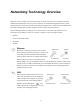
Networking Technology Overview When two or more computers are connected so they can “talk” with each other, a computer network is established. Individual users can now connect to Web servers worldwide through the Internet, a global computer network. A local area network (LAN) enables computer users in a business or household to share files without trading disks, and share peripherals such as printers and external drives.
Home Phoneline Networking (HomePNA) The Intelligent Gateway supports the Home Phoneline Networking Alliance protocol. HomePNA technology lets you connect computers in different rooms using your home’s existing telephone wiring. To create a home phoneline network, you need an external HomePNA adapter for each additional computer you connect to the network using HomePNA. These devices make it possible to connect each additional computer through the phoneline.
Plan your network The following diagram shows a recommended location for the Intelligent Gateway and your computers. Place the Intelligent Gateway in a visible, easily accessible location near the power mains, telephone socket, and a computer. If your office computer has Windows 98, ME, 2000, or XP, we recommend connecting it via Ethernet. For two computers, consider using USB and Ethernet.
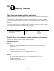
Step 1 Getting Started First: Remove or disable conflicting applications Applications that enable a computer to share its Internet connection (often called Internet sharing software) and PC based firewall applications typically interfere with the Intelligent Gateway and should be removed or disabled before you install the Intelligent Gateway.
Browser Requirements Windows: Microsoft Internet Explorer 5.0 or higher (Internet Explorer 6.0 is included on the Intelligent Gateway Setup Wizard CD) or Netscape Navigator 4.7 or higher. Macintosh: Microsoft Internet Explorer 5.0 or Netscape 4.74 or higher. Third: Install your ADSL Filter Because telephony and DSL signals are carried between the exchange and your office over the same cable, filters are needed to split the signals within your office.
Step 2 Connect Your First Computer to the Intelligent Gateway Choose a computer and connection type The first computer you connect to your local network is used to configure the Intelligent Gateway for proper operation, and should be located in the same room as the Intelligent Gateway. Choose one of the following methods to connect your first computer to the Intelligent Gateway. Save and close all open programs before you begin connecting your Intelligent Gateway. Connection Type Go to...
Ethernet Connection Requires a computer with an Ethernet port 1. Connect the provided AC power adapter from the Intelligent Gateway’s POWER port to an electrical outlet. The green POWER light on the front of the Intelligent Gateway should light up. 2. Connect the provided Ethernet cable from any available LOCAL ETHENET port on the Intelligent Gateway to your computer’s Ethernet port. 3. Connect the provided ADSL Filter to the telephone socket. 4.
USB Connection Requires a computer with an available USB port. Refer to the note below for exceptions. Note: Only one Windows or Macintosh computer can be directly connected to the Intelligent Gateway using the USB connection. Intelligent Gateway USB connectivity is NOT available for Macintosh OS earlier than 8.6, Mac OS 10.0, Mac OS 10.1, Windows 95, Window 95 OSR2, or Windows NT. Additional computers may be added to the network using connection options such as Ethernet. 1.
Install the Intelligent Gateway USB driver — Windows PC Before installing your Intelligent Gateway software, you must install the Intelligent Gateway USB driver on your computer. The following screens show the installation under Windows XP and may vary somewhat on Windows 98, Windows ME, and Windows 2000. 1. Power on your computer. When the Found New Hardware Wizard window opens, make sure that Install the software automatically (Recommended) is selected and click Next to continue. 2. The driver installs.
Install the Intelligent Gateway USB driver — Macintosh Before installing your Intelligent Gateway software, you must install the Intelligent Gateway USB driver on your computer. The following screens show the installation under Macintosh OS 10.2 and may vary somewhat on Macintosh OS 8.6 to 9.X. 1. Power on your computer. 2. Insert the Intelligent Gateway Setup Wizard CD in your computer’s CD-ROM drive. 3. Double-click the 2Wire USB folder to install the driver. 4.
8. Verify that Ethernet Adaptor (en1) is selected in the Show field. If it is not, select it from the pull-down menu. When the New Port Detected message displays, click OK. 9. Click Save to complete your installation. Note: Your Macintosh computer automatically assigns the name “(en1)” to the Intelligent Gateway USB port. If your computer has more than one Ethernet-type network device installed, the USB port may be named “(en2)” or higher. Check your connections Power-on your computer.
Step 3 Install the Intelligent Gateway Software Before installing the Intelligent Gateway software, it is very important that you disable any conflicting applications such as firewall and file- and printer-sharing applications. See Step 1, “Getting Started.” BT Openworld Pay-As-You-Go Dial Up Connection Option Before installing the Intelligent Gateway software, please make sure that you have your username, password, and email address that were provided in your Welcome Letter and via email.
Installing the Intelligent Gateway Setup Wizard on Windows PCs Note: Close all programs before running the Intelligent Gateway Setup Wizard. The Intelligent Gateway software must be installed on all computers in your network. Place the Intelligent Gateway Setup Wizard CD in the CD-ROM drive of your computer and follow the onscreen instructions. It may take up to one full minute for the Setup Wizard to start.
Configuring the Intelligent Gateway on Macintosh computers Refer to the “Welcome Letter” that was included in you Intelligent Gateway package. It provides the key code you will need to configure the Intelligent Gateway on your Macintosh computer. Macintosh 8.6 and 9.x 1. Click the Apple menu and select Control Panel>TCP/IP. The TCP/IP menu opens. 2. From the Connect via dropdown, select the method by which the Intelligent Gateway will connect to your computer (Ethernet, PC Port, or wireless). 3.
Step 4 Add Computers to the Network Choose a computer and connection type After your first computer is connected to the Intelligent Gateway and your Internet connection has been established, it is time to connect the other computers to the network. Use any or all of the following methods to connect additional computers to your network: Connection Type Go to... Ethernet Requires a computer with an Ethernet port. Recommended for small office environments using Ethernet (Category 5) wiring.
Ethernet Connection Requires a computer with an Ethernet port 1. Connect an Ethernet cable from any available LOCAL ETHERNET port on the Intelligent Gateway to your computer’s Ethernet port. Repeat Step 3 “Install the Intelligent Gateway Software” on page 12.
USB Connection Requires a computer with an available USB port. Refer to the note below for exceptions. Note: Only one Windows or Macintosh computer can be directly connected to the Intelligent Gateway using the USB connection. Intelligent Gateway USB connectivity is NOT available for Macintosh OS earlier than 8.6, Mac OS 10.0, Mac OS 10.1, Windows 95, Window 95 OSR2, or Windows NT. Additional computers may be added to the network using connection options such as Ethernet. 1.
Home Phoneline Networking (HomePNA) Connection If a telephone is located in the same room in which the PC Port will be installed Computers connected with HomePNA access the Internet connection on the Intelligent Gateway and other computers on the network using existing telephone wiring. You will need one PC Port for each computer that you are connecting through HomePNA. 1. Connect the provided ADSL Filter to the telephone socket. 2.
\ Home Phoneline Networking (HomePNA) Connection If there is no telephone located in the room in which PC Port will be installed Computers connected with HomePNA access the Internet connection on the Intelligent Gateway and other computers on the network using existing telephone wiring. You will need one PC Port for each computer that you are connecting through HomePNA.
Wireless Connection Requires a computer with an 802.11b wireless network adapter installed and a 2Wire Wireless PC Card installed in the Intelligent Gateway. Wireless adapters are purchased separately from the Intelligent Gateway. 1. Install your wireless adapter according to the instructions included with your adapter. 2. Configure your wireless adapter. Your Intelligent Gateway is configured with unique security parameters that must be configured into your wireless adapter.
4. Set the wireless network name (also referred to as SSID). The wireless network name of your Intelligent Gateway is 2WIRE in all capital letters, followed by the last three digit of the Intelligent Gateway serial number located on the bottom of your Intelligent Gateway. For example, if the last three digits of your Intelligent Gateway serial number are 102, your Intelligent Gateway network name would be 2WIRE102.
Using the Intelligent Gateway Network The Intelligent Gateway user interface allows you to check the status of your network, assign permissions to other users on the network, and access links to the most commonly used features of your Intelligent Gateway. After you have connected your computers to your network and installed the Intelligent Gateway software, enter http://home in the address bar of your browser. The Intelligent Gateway user interface opens.
System The System pages provide you with general system information and operational status. • The Summary page is your system home page. You can access this page by clicking the HOME icon from any system page. The Summary page provides summary information and links to the most commonly used features of your system. • The System Password page allows you to password protect local access to your system settings, preventing users on your local network from changing your system configuration.
Editing your system password If a system password has been set, the system will prompt you to enter the password when accessing any page where you can change settings. If a password has not been set, a reminder notice is displayed in some of the more sensitive topic areas. Setting a system password will ensure that only you are permitted to make changes to your system settings. Setting a password To set your Intelligent Gateway system password: 1. Check the Enable checkbox. 2.
Editing your date and time settings The Intelligent Gateway automatically sets the time using time servers on the Internet, or from the PC if no Internet connection is available. It retrieves date/time information in Greenwich Mean Time (GMT). Your local time is set using the Time Zone setting you configured when you set up your system. If your wish to change your time zone: 1. In the Settings panel, select a time zone from the pull-down menu. 2. Click the SAVE button.
Broadband Link The Broadband Link pages show general information about your broadband link connection and system configuration, and allows advanced users to manually configure their DSL and Internet connection settings. Viewing your Broadband Link summary The Broadband Link Summary page provides general information about the current status and speed of your broadband link connection, and your system configuration.
Viewing connection details Click the View connection details link to view technical information about your broadband connection. This information is used by technical support representatives to aid them in troubleshooting a problem with your broadband connection. DSL connection details The DSL Connection Details panel shows the following information: Field Description DSL Line (Wire pair) The DSL signal is primarily transmitted on Line 1 (inner pair).
Field Description Current Output Power The current DSL transmit power of your system. The level is measured in decibels (dBs). DSLAM Vendor Information A DSLAM is the piece of equipment located in the Telephone Exchange that provides the DSL signal to your DSL line. The Vendor Information identifies information about the configuration of this equipment. PVC Info Displays the pair of numbers that uniquely identifies the ATM virtual circuit between the system and the provider of your DSL service.
Field Description Secondary Domain Name Server The Secondary Domain Name Server is used as a backup if the Primary server fails to respond. If you receive your Internet Address settings automatically, the subnet mask has been set for you. If you manually set your Internet Address (static IP) this is the information that was provided to you by BT Openworld and entered by you during system installation. This parameter may not be necessary and may be left blank.
Monitoring your Internet connection Click the Monitor Internet connection link to launch the Speed Meter.The Speed Meter measures the actual rate at which data is coming into (Incoming Kbps) and going out of (Outgoing Kbps) your system. It measures real-time data throughput in Kilobits per second and displays in one-second intervals.
Viewing Broadband Link statistics The Intelligent Gateway keeps a running count of DSL activity in and out of your Internet connection since the last reset, and tracks errors that occurred on your DSL connection. The Transmit and Receive Data panel shows the total number of data bytes and IP packets either transmitted or received, and the total number of IP errors transmitted and received since the last reset.
Modifying Broadband Link settings The Advanced Settings page allows advanced users to manually configure their DSL and Internet connection settings. You should only modify the connection settings if you are very familiar with DSL and networking technology.
Local Network The Local Network pages show summary information about the devices in your network, and allow you to configure the devices. Viewing Local Network summary information The Local Devices panel displays the name of the device, how it is connected, any special configuration information, and gives you links to other system features that you can set up for the device. The following information may display: • Device. The device symbol is represented with a computer icon.
The box to the right of the Local Devices panel contains links to other system features that can be viewed or configured for this device. Certain links may not apply for each device. The following lists the possible links: • Access shared files. Click this link to access the shared files available from this computer. This feature only works with Microsoft Windows computers that have shared files and file sharing configured. • Edit firewall settings.
• Private Network. Sets the IP address range used by the local network. You can choose from three standard configuration options or configure the network settings manually. If you choose manual configuration, you must understand IP internetworking thoroughly. An incorrect configuration can cause unpredictable results on your local network.
Computers that are assigned non-routable (private network) addresses will use Network Address Translation (NAT) to access the Internet. Choosing a “DHCP Fixed” entry instructs the Intelligent Gateway to always provide the same address from the DHCP pool to the specified computer. Note: Computers on either the Public Network or Bridge Network are still behind the firewall. To allow inbound traffic to these computers, you must modify the firewall settings specified for that computer.
1. Open the Intelligent Gateway home page. 2. Click the Local Network tab.
3. Click Advanced Settings. 4. In the Settings pane, change the LAN IP range to either 10.xxx.xxx.xxx or 192.xxx.xxx.xxx by clicking the corresponding radio button. 5. Click the SAVE button. You must release and renew the IP address on your computer for the change to take effect. Maintaining/restoring the VPN connection If your VPN client regularly loses its connection, you can increase the time before the computer requires a new IP address by following these steps.
1. Open the Intelligent Gateway home page. 2. Click the Local Network tab.
3. Click Advanced Settings. 4. In the Settings pane, increase the DHCP timeout period to 24 hours by entering “24” in the Set DHCP Lease field. 5. Click the SAVE button. As an alterantive to increasing the DHCP timeout, you can assign static IP addresses to the computer. Because the method for assigning static IP addresses depends on the computer operating system, refer to the documentation that came with your computer.
network. You can configure the firewall to allow specific application traffic from the Internet to pass through to a computer on your local network. If the firewall has been configured to allow traffic from the Internet to pass through, the device and the allowed application are listed. If application traffic is allowed, external users on the Internet can have limited access to your local network.
the TCP protocol and Port 2999. The system recognizes that the data on Port 2999 (or a range of ports) is required for the specified application, and routes it accordingly. Click EDIT SETTINGS to access a page where you can map an application to a computer that will allow traffic through the firewall. The Firewall Monitor panel provides a summary of recent attacks blocked by your firewall.
Editing your firewall settings The Firewall Settings page allows you to configure the firewall to pass through specific application data to a selected computer. If you want to host an application on your network for Internet users to access (such as a Web server), you must configure your firewall to allow users on the Internet to access it. To do so: 1. From the Select a computer pull-down menu, select the computer. 2. Select the Allow individual application(s) radio button. 3.
Updating your Application Profile list If the application you want to host does not appear in the Application Profile list, you may need to update your application list. If an update is available, click the UPDATE APPLICATION LIST button above the list of application profiles. Creating, editing, or deleting your Application Profile If the application that you want to host is not included in the updated application list, you may need to create your own application profile.
8. Repeat the previous step for each port or range of ports required for the application profile. 9. Click DONE. To edit application profiles that you have created, select the profile from the list and click the EDIT button. This launches the Edit Application Profile panel. To delete an application profile, select the application profile from the list and click DELETE.
To disable DMZplus mode: 1. Select the computer for which you wish to disable DMZplus. 2. Select Maximum protection. 3. Click DONE. 4. Access the computer that is in DMZplus mode. 5. If the computer will continue to automatically obtain an IP address, restart the computer. If the computer will have a static IP address, configure it with a valid static IP address and then restart it.
Editing advanced firewall settings Advanced firewall configuration allows advanced users to further configure the system software firewall. You should use this feature only if you have advanced knowledge about firewalls and networking. If an Inbound box is checked, the firewall allows the corresponding protocol to pass through from the Internet to the network. If an Outbound box is checked, the firewall allows the traffic from the network to pass through the firewall to the Internet.
Firewall Monitor The Firewall Monitor enhanced service extends the professional-grade firewall capabilities of your Intelligent Gateway by continuously assessing threats to your home network. Using the Firewall Monitor service, you can: • Automatically download updates to your firewall software to protect against new threats. • Receive on-screen notification to alert you of network attacks. • Review details about attacks blocked and the source of the attacks.
Click the VIEW NOW button to display the Monitor Your Firewall page where you can customize these settings for your firewall. The Monitor Your Firewall page contains four areas: • Top Attackers • Attacks Blocked • Firewall Rule Database • Attack Alerts Configuring/editing attack alerts To configure the Attack Alerts criteria, click EDIT SETTINGS.
The Edit Attack Notification Settings page opens. Enabling attack notification To enable the attack notification function, make sure the Attack Notification Enable checkbox is checked. If you wish to disable this function, uncheck the checkbox. When you are finished setting your attack notification criteria, click SAVE for your notifications rules to take effect. Configuring notification rules To be notified of attacks on the Intelligent Gateway home page, you must set up notification rules.
• Time Duration. Select the time duration. If the number of attacks specified is exceeded within the chosen duration, you are notified. Choices include one day or one week. A week is defined as Monday at midnight to Sunday at midnight. Enabling email notification In addition to being notified of attacks on the Intelligent Gateway home page, you can be notified via email when one of your attack threshold rules has been exceeded.
Viewing Firewall Monitor attack alerts After setting up alert notification, if your network firewall is attacked meeting the criteria set, notice of the attack is provided on the Intelligent Gateway home page, in the Firewall area. Click the VIEW NOW button to display the Monitor Your Firewall page and view attacks made to your network firewall.
Viewing top attackers The Top Attackers area of the Monitor Your Firewall page displays the IP address and domain of each top attacker. The attackers are ranked based on the number and severity of attacks. To see the details of a particular top attacker, click the View Details link of the attacker you wish to view. The View Attacker Details page opens.
Your Firewall Monitor will give you details about each potential attack, including its source address. BT Openworld can ONLY investigate attacks that originate from our address space. Customers who originate attacks from our address space are not complying with our terms and conditions, and may have their account terminated. If an attack originates from BT’s address space, “BT” will be displayed in the attacker domain column in the Top Attackers List.
The View Your Detailed Firewall Log page opens. To clear the log, click CLEAR LOG. To return to the Monitor Your Firewall page, click your browser BACK button. Understanding the Firewall Rule Database area The Firewall Rule Database area of the Monitor Your Firewall page shows you the current firewall rules version running on your Intelligent Gateway. It also shows you when the rules were last updated. To display the firewall rule database update log, click VIEW LOG.
Updating your firewall rules Updated firewall rules are automatically downloaded to your Intelligent Gateway after you purchase the Firewall Monitor service. The Firewall Monitor application typically checks for new updates every 24 hours.
Access Controls Access Controls combines two full-featured applications that create an easy-to-use solution to keep your office running smoothly: • Internet Access Restriction • Content Screening Access Controls provides whole-network service. The password protected restrictions and schedules you set are managed at the Intelligent Gateway rather than through individual PCs.
Setting up Internet Access Restriction The SET UP NOW button appears on the right side of your Intelligent Gateway home page in the Access Controls area. • To begin configuring the Internet Access Restriction feature, click SET UP NOW. • The Set Up Internet Access Restriction page opens. • Read the Introduction for a summary of Internet Access Restriction features and configuration setup sequence.
• Click NEXT to see the Internet Access Restriction Schedule and begin defining schedules for the computers on your network. Note: Initially, all computers set up on your local network default to have full access to the Internet. Step 1: Define Internet Access Restriction settings For each computer on the network, you can block access to all Internet applications or block access to specific types of applications (such as Instant Messaging or Web browsing).
The Edit Internet Access Restriction Settings page opens. The upper portion of the page displays the summary of restrictions that are applied to the selected computer. The lower portion of the page is used to modify the restriction schedules of each category for this computer.
• Allow Instant Messaging - Choosing the instant messaging category allows access to common instant messaging applications, such as AOL Instant Messenger™, Yahoo Messenger™, and ICQ™. All other Web services are not active, including Web browsing. • Allow All Other Applications - Choosing the All Other Applications category permits all other application types, except Web browsing and Instant Messaging unless allowed under other categories.
Viewing a restriction schedule To view the restriction schedule for a specific computer, from the Select a Computer dropdown list, select the computer name. The page is automatically updated to display the restriction schedule for the selected computer. This page displays the restrictions applied to each computer on your network.
Content Screening The Content Screening section of the Access Control application provides the highest level of protection available by: • Providing access to sites that you have defined as approved. • Blocking or limiting access to specified sites and allowing creation of a list of approved sites for employee browsing. • Safeguarding your office from Web sites promoting objectionable content.
Setting up Content Screening To configure Content Screening, click the SET UP NOW button on the right side of your Intelligent Gateway home page in the Access Controls area.
Step 1: Block content categories for this screening group After initiating the set up for Content Screening, the Block Content Categories for This Screening Group page opens. Use this page to set up the blocked content category for Screening Group 1. Content categories To make it easier to block undesirable content, a number of content categories have been developed. Professional researchers working with a third-party maintain a database of Web site addresses that fall under specified content categories.
Note: Sites discussing medicinal drug use, industrial hemp use, or public debate on the issue of legalizing certain drugs are not blocked, nor are sites sponsored by a public or private agency that provides educational information on drug use. • Gambling • Hate Speech Note: Sites that contain news, historical, or press incidents are not blocked. • Violence Note: Sites that contain news, historical, or press incidents are not blocked.
Adding sites To add a site to either the blocked or approved list, enter the address of the Web site in the Block Sites box or the Approve Sites box and click ADD. Note: When adding a specific site to either list, you can exclude the http://www portion of the address. For example, if you are adding http://www.abc.com to either list, you need only enter abc.com. Removing sites To remove a Web site from one of the lists, highlight the site and click DELETE.
Viewing Content Screening settings Use the View Content Screening Settings page to view the current content screening settings for your network. The Content Screening Summary Page displays: • The computer assigned to each group. • The categories of blocked content for each group. • Additional sites that are blocked for viewing. • Additional sites that are approved for viewing.
3. Click LOG to view the Access Controls log. To clear the log, click the CLEAR LOG button, located in the corners of the right side of the page.
Sharing Files and Printers PC/network configuration for file sharing This chapter describes how to set up a network for file / printer sharing between PCs. If wireless networking is being added to an existing network (especially where network login is required) please check with your network administrator / consultant before making any changes. Windows 95, 98, 98 SE operating systems Adding PCs to your network After you have set up your network, you now need to add each PC to the network. 1.
2. The Network Properties screen opens. Select Client for Microsoft Networks and then click the Properties button. 3. Ensure that the Logon validation fields are empty, and that the Logon and restore network connections radio button is selected. Click OK.
4. Click the Identification tab. In the Computer name field, enter a name for your computer. In the Workgroup field, enter a workgroup name. Do NOT click OK. 5. Click the Access Control tab. In the Control access to shared resources using field, click the Share-level access control radio button. Do NOT click OK.
6. Click the Configuration tab. In the Primary Network Logon field, ensure that Windows Logon is selected in the pulldown. Click the File and Print Sharing button. 7. Check the I want to be able to give others access to my files checkbox and click OK. 8. File and print sharing will now appear in your network components. Click OK for Windows to update your settings. 9. Restart your PC when prompted.
Accessing PCs on your network 1. After you have configured file sharing on your PCs, double-click the Network Neighborhood icon to verify that you can see them. 2. In Network Neighborhood, double-click Entire Network. 3. In Entire Network, your network name should appear as an icon. Double-click the icon. 4. The PCs on your network will be displayed as shown in the screen capture. When file sharing is set up, you will be able to browse the available content of these PCs.
Sharing your files After you have configured file and print sharing, you can choose a drive or folder to share with the other users on your network. 1. Open My Computer. Locate your chosen drive or folder and right click it, then click Sharing. 2. In the Sharing tab, click the Shared As radio button. In the Shared Name field, enter a share name (or accept the default). In the Access Type field, click the radio button next to your access preference (Read-Only, Full, or Depends on Password).
Windows ME operating systems Adding PCs to your network 1. Double-click the My Network Places icon to open the My Network Places window. 2. Double-click Home Networking Wizard. 3. When the Wizard opens, click Next to continue. 4. Select the Yes, this computer uses the following: radio button then select the A direct connection to my ISP using the following device radio button. Click Next.
5. In the Computer name field, enter a suitable name for your computer. In the Workgroup Name field, select the Use the Workgroup name radio button and enter the name of your workgroup (all PCs on your network must have the same workgroup name). Click Next to continue. 6. Leave the Share files and printers screen blank and click Next. 7. Select the No, do not create a network disk radio button and Next to continue.
8. Click Finish to complete your network setup. 9. Restart your PC when prompted. Accessing PCs on your network 1. To check that your are connected to the other PCs on your network, double-click the My Network Places icon. 2. Double-click Entire Network. 3. An icon will be displayed with your network name. Double-click this icon.
4. The PCs on your network will be displayed. When file sharing is enabled, you can browse the available content of these PCs. Note: If you have just added a new PC to the network, you may need to select View>Refresh before this will be shown as part of the network. Sharing your files 1. Right-click My Network Places and click Properties. 2. In the Configuration tab, click the File and Print Sharing button.
3. Select the I want to be able to give others access to my files radio button and click OK. 4. File and printer sharing will now appear in your network components list. Click OK and restart the PC when prompted. 5. When your PC has restarted, open My Computer and locate the drive or folder you wish to share. Right click this drive/folder and click Sharing.
6. Select the Shared As radio button. In the Share Name field, enter a suitable share name (or accept the default). In the Access Type field, click the radio button next to your access preference (Read-Only, Full, or Depends on Password). In the Password field, enter a password if you wish to limit user access, or leave the Password field blank for no password required. Click Apply and then OK to exit.
3. Double-click Microsoft Windows Network. 4. An icon should be present with your network name. Double-click the icon. 5. The PCs that are in your network will be displayed. When file sharing is set up, you will be able to browse the available content of these PCs. Sharing your files In Windows NT, file sharing is automatically set up when networking is configured; however, automatic access permissions are set.
1. Double-click My Computer. For each drive that has the Sharing (hand) symbol, right click that drive and click Sharing. 2. In the Sharing tab, select the Not Shared radio button and click Apply. Click OK to exit. 3. You can now add the other computers you wish to share to your User Group. From the Start menu, select Programs > Administrative Tools > User Manager.
4. In User Manager, click User and then New User. 5. In the Username field, enter the computer name. This name must be identical to the one you entered in Network Properties. In the Password field, enter a password. To make it easy to remember the password, you can use the same password with which the PC logs on to the network. Alternatively, you can leave the Password field blank so that no password is required to access folders.
7. In My Computer, locate and right-click the drive or folder you wish to share and click Sharing. Click the Shared As radio button and in the Share Name field, enter a Share Name (or accept the default). Click the Permissions button. 8. In the Access Through Share Permissions screen, click the Add button. The Add Users and Groups window opens. 9. For each user that you wish to add, find the user’s PC on the network (if it is not present, click Show Users).
10. As you add each user, use the Type of Access pull-down menu to assign the type of access you wish each user to have (for example, Full Control or Read-Only). When all users appear in the Add Names window, click OK. 11. Click OK to exit Share Permissions. Windows 2000 operating system Adding PCs to your network 1. Before you add PCs to your network, you must first ensure that networking is enabled. Rightclick My Network Places and click Properties.
2. Networking is enabled if the Local Area Connection icon is present. If it is not present, double-click Make New Connection and follow the on-screen instructions. 3. When you double-click the Local Area Connection icon, the Local Area Connection Status screen opens. 4. After networking is enabled, you can change your Workgroup name to that of your new network. To do so, right-click My Computer and click Properties.
5. Select the Network Identification tab and click the Properties button. 6. In the Computer name field, enter a name for the computer. In the Workgroup field, enter a name for the workgroup and click OK. 7. The Network Identification welcome screen opens. Click OK, then close the Network Identification screen and restart your PC when prompted. Accessing PCs on your network 1. To verify that your are connected to the other PCs on your network, double-click the My Network Places icon.
2. Double-click Entire Network. 3. Click the entire contents link. 4. Double-click the Microsoft Windows Network icon.
5. Double-click the icon with the name of your network. 6. The PCs in your network will be displayed. When file sharing is enabled you will be able to browse the available content of these PCs. Sharing your files 1. In Windows 2000, before you can share files with other users you must add the other PCs to your User Group. To do so, from the Start menu select Settings> Control Panels.
2. Double-click the Administrative Tools icon. 3. Double-click the Computer Management icon. 4. Click Local Users and Groups and then click on the Users folder to highlight it. Click the Action button, then click New User. 5. The New User screen opens. In the User name field, enter the name of the computer you wish to add. The name must be identical to the name that the PC uses in its network properties. In the Password field, enter a password (recommended).
6. The name of each user you have added will now appear in the Users section of the Computer Management screen. 7. When you have added all users, you can now specify sharing on your chosen drive or folder. To do so, locate your drive or folder, right-click it and click Sharing. 8. The Local Disk Properties screen opens. Select the Sharing tab. In the Share name field, enter a suitable name for the drive or folder (or accept the default one) and then click the Permissions button.
9. The Permissions for window opens. Click the Add button. 10. For each PC with which you wish to share a folder, locate the users in the Select Users, Computers, or Groups window and click the icon, then click the Add button. Repeat this for each PC with which you wish to share the folder, and then click the OK button. 11. The users will now appear in the Permissions for window. Click each user icon and assign their access rights in the Permissions field (Full Control, Change, or Read).
Printer sharing Sharing your printer (Windows 95, 98, and 98 SE) Print sharing as host 1. Right-click Network Neighborhood and click Properties. 2. The Network window opens. In the Configuration tab, click the File and Print Sharing button. 3. The File and Print Sharing window opens. Click the I want to be able to allow others to print to my printer(s) checkbox and click OK. 4. Click OK on the Network Properties screen and restart you PC when prompted.
5. When your PC has restarted, from the Start menu select Settings> Printers. 6. The Printers window opens. Right-click the printer you wish to share and click Sharing. 7. In the Sharing tab, click the Shared As radio button. In the Share Name field, enter a share name for the printer. In the Password field, enter an access password (optional). Click the Apply button, and then OK to exit.
Print sharing as client 1. When one of your network PCs has a printer configured for sharing, you must add this printer to the printer settings of each PC before they can print to it. From the Start menu, select Settings> Printers. 2. The Printers window opens. Double-click the Add Printer icon to start the Add Printer Wizard. 3. Click Next to continue. 4. Click the Network printer radio button and click Next.
5. Click the Browse button to locate the networked printer. 6. Locate the PC to which the printer is attached. Click the printer icon, then click OK. 7. The network path now displays in the Network path or queue name field. Click Next to continue.
8. The next screen prompts you to select the make and model of your printer. In the Manufacturers scroll list, select your printer by make. In the Printers scroll list, select your printer by model, then click Next. If your printer is not displayed, then click the Have Disk button and insert your printer disk. 9. If you were required to use your printer disk, you will be prompted to enter the location of the printer files (usually the drive letter for whichever drive you are using).
12. The following confirmation screen opens. Your test page should start printing within less than 60 seconds. If your test page prints successfully, click Yes. If it does not print successfully, click No to open a troubleshooting tool. 13. If your printer has been set up correctly, it will now appear in your Printers folder. Sharing your printer (Windows ME) Print sharing as host 1. Right-click the My Network Places icon and click Properties.
2. The Network window opens. In the Configuration tab, click the File and Print Sharing button. 3. Click the I want to be able to allow other to print on my printer(s) checkbox and click OK. 4. In the main Network Properties window, click OK and restart your PC when prompted. 5. When your PC has restarted, from the Start menu select Settings > Printers.
6. The Printers window opens. Right-click the printer you wish to share and click Sharing. 7. The Printer Properties window opens. In the Sharing tab, click the Shared As radio button. In the Share Name field, enter a suitable name for the printer. In the Password field, enter a password (optional) and click the Apply button. Click OK to exit. In your Printer folder, the printer will now have the shared (hand) symbol and will be available to everyone on your network. Print sharing as client 1.
2. The Printers window opens. Double-click the Add Printer icon to open the Add Printer Wizard. 3. Click Next to continue. 4. Click the Network printer radio button and click Next to continue. 5. Click the Browse button to locate your network printer.
6. In the Browse for Printer window, click your printer to select it and click OK. 7. The network path for your printer is now displayed in the Network path or queue name field. Click Next to continue. 8. If the following screen appears, click the Keep existing driver (recommended) radio button. Click Next to continue.
9. In the Printer name field, enter a suitable name for your printer. If you want Windows-based programs to use this printer as the default, click the Yes radio button. Click Next to continue. 10. You will be prompted to print a test page. To print a test page, click the Yes (recommended) radio button and click Finish. 11. The following confirmation screen opens. Your test page should start printing within less than 60 seconds. If your test page prints successfully, click Yes.
13. The printer will now appear in your Printer folder. Sharing your printer (Windows NT) Print sharing as host 1. From the Start menu, select Settings> Printers. 2. In the Printers folder, locate the printer you wish to share, right-click it and click Sharing.
3. The Printer Properties window opens. In the Sharing tab, click the Shared button. In the Share Name field, enter a suitable name for your printer. To install drivers for other users on different operating systems, you can select these in the Alternate Drivers scroll list. Click OK. The printer will now have the shared (hand) symbol and will be available to everyone on your network. Print sharing as client 1. From the Start menu, select Settings> Printers. 2.
3. Click the Network printer server radio button and click Next. 4. Browse through your network to find the PC connected to your printer, then click the printer to highlight it and click OK. 5. If the drivers for the printer are not already installed, the following message may display. Click OK. 6. The next screen prompts you to select the make and model of your printer. In the Manufacturers scroll list, select your printer by make.
7. Click the Browse button to locate your CD- ROM drive and then click OK. 8. If you want Windows-based programs to use this printer as the default, click the Yes radio button. Click Next to continue. 9. The last screen confirms that the printer has been successfully installed. Click Finish to exit. 10. The printer will now appear in your Printer folder.
The Intelligent Gateway Indicator Lights Intelligent Gateway indicator and status lights The Intelligent Gateway has three indicator lights that can be used to diagnose installation and connection problems. The following tables describe how to interpret the POWER, BROADBAND LINK, and LOCAL NETWORK lights. Power light Operating state OFF The Intelligent Gateway is not getting power. Blinking green The Intelligent Gateway is powering up. Solid green Power is on. Solid red System error.
Diagnosing connection problems This section describes some connection problems you may encounter with your Intelligent Gateway network and provides suggestions for solving those problems. If the problem you are having is not covered here or in the Help system, or if the suggestions provided do not solve the problem, call the Technical Support number provided with your Intelligent Gateway.
Frequently Asked Questions This chapter provides frequently asked questions about installation, networking, and Intelligent Gateway configuration and management. Installation FAQs What is the best way to connect a second PC to my Intelligent Gateway network? There are four different ways you can connect a computer to your Intelligent Gateway: Ethernet, HomePNA, direct connect USB, and Wireless. Each connection type has advantages in different circumstances.
• How far is the computer from the Intelligent Gateway? If the second computer is in the same room, there should be no constraints on a wireless connection. For a direct USB connection, the computer must be within six feet of the Intelligent Gateway. With Ethernet or HomePNA, a cable of appropriate length will be necessary. If the second computer is not in the same room as your Intelligent Gateway, consider the following: • Ethernet requires a special cable (Category 5 - Unshielded Twisted Pair).
To connect using USB, you must have a USB cable (a six foot, light gray USB cable is provided with your Intelligent Gateway), the Intelligent Gateway Setup CD, and a computer with an open USB port, running Windows 98, 98SE, ME, 2000, or XP, or Mac 8.6 to 9.x or 10.2 or higher. Note: Windows 95, NT, and other versions of Macintosh computers are not supported for direct connect USB.
Networking FAQs How can I change my network IP range? You can change the IP address range used by the Intelligent Gateway network by following these steps: 1. From the Intelligent Gateway home page, click the Local Network tab on the top of the Intelligent Gateway user interface. 2. Click the Advanced Settings tab. 3. In the Settings panel, select the IP address scheme you want to use or define your own. 4. Click the SAVE button.
3. In the Broadband Network Username field, enter your PPPoA username. 4. In the Password field, enter your PPPoA password. 5. In the Confirm Password field, re-enter your password. Computer Configuration FAQs How do I set my browser’s home page to the Intelligent Gateway user interface? To set your browser’s home page to the Intelligent Gateway user interface, find the place in your browser to set the home page address and enter //gateway.2wire.
Where can I obtain drivers for my network adapter? There are four places to look for network adapter drivers: • On the CD that came with your network adapter. • On the CD that was provided with your adapter installation instructions. If your network adapter was provided to you with your Intelligent Gateway, the drivers may be integrated with the Intelligent Gateway installation CD. • In the Support section of the 2Wire Website: //www.2Wire.
1. Right-click the Microsoft Outlook desktop icon and select Properties. 2. Click Add and select the Manually configure information services radio button. Click Next. 3. Leave the default Profile Name and click Next.
4. The Add Services to Profile window opens. Select Internet E-mail and click OK. 5. The Mail Account Properties window opens. Note: If Microsoft Outlook has previously been configured, the preceding steps will be skipped. In this case the first step will be to click the Add button and then select Internet E-mail. 6. In the Mail Account field, enter the name you want displayed for the email account. In the E-mail address field, enter the email address of the account you are setting up.
Openworld primary mail account, the email address is supplied in your Welcome Pack. You can also enter information in the Name and Organization fields at your discretion (optional). 7. Click the Servers tab. In the Incoming mail (POP3) and Outgoing mail (SMTP) fields, enter the incoming and outgoing mail addresses. If you are setting up a BT Openworld mail account, enter mail.btconnect.com.
9. Click the Connection tab. Click the Connect using my local area network (LAN) radio button. Click OK. Depending on the current set-up of Microsoft Outlook, you may need to add a personal folder so Microsoft Outlook knows where to store mail. If Microsoft Outlook has previously been configured, this may not be necessary. To add a personal folder, follow these steps.
1. Right-click the Microsoft Outlook desktop icon. Select Properties. 2. In the MS Exchange Settings Properties window, click Add. 3. In the Add Service to Profile window, select Personal Folders and click OK.
4. In the File name field, enter a name for the folder. 5. Click OK. 6. Click OK to conclude set-up.
To verify your set-up, double-click on the Microsoft Outlook desktop icon to run Microsoft Outlook. Verify that the Inbox is displayed. Click Send/Receive to collect email. Check for any error messages. How do I set my browser to accept cookies? Warning: Changing your cookie settings may have privacy and security implications. Make sure you understand these implications before changing your cookie settings. Following is detailed information for specific browsers: PC — Internet Explorer 6.0 1.
Macintosh — Internet Explorer 5 1. From the menu bar, select Edit > Preferences. 2. Select Receiving Files / Cookies in the menu on the left side. Macintosh — Netscape 4.7 1. From the menu bar, select Edit > Preferences. 2. Select Advanced from the menu on the left side. How do I configure my wireless card for a static IP address? The Intelligent Gateway supports both Dynamic and Static IP addressing on your Intelligent Gateway network.
How do I know whether my PC has a network adapter that can work with the Intelligent Gateway? In a Microsoft Windows computer you can check to see if you have a network adapter installed in your computer by accessing the Control Panel and clicking the Network Control application. If an Ethernet, HomePNA, or 802.11b wireless adapter is listed, it can be used to connect to your Intelligent Gateway network. On a Macintosh computer, access the Control Panel and select TCP/IP.
How do I access the Intelligent Gateway management page? The Management and Diagnostic Console (MDC) is used for advanced troubleshooting. It can be accessed by entering //homeportal/management in the browser address bar. What is the maximum number of ports that I can open for a game? You can have up to 64 entries in the firewall pass-through table. If you have one port per entry, you can have up to 64 ports opened.
general consumer operating systems such as Windows. It is a hardware firewall that provides a level of protection that cannot be afforded by a firewall running on a networked computer. Because the Intelligent Gateway is optimized for networking and firewall functions, it can perform with greater efficiency than Windows and without slowing the performance of your computer.
Will I be able to use Windows XP Professional Remote Desktop (Remote Assistance) if the XP computer to be controlled is behind an Intelligent Gateway? Yes. Windows XP Professional allows you to connect to another computer. Once connected, you can send chat messages, view screens, and remotely control the other computer.
Glossary A Access Point. A device that transports data between a wireless network and a wired network. With the help of the system, a wireless base station is an example of an access point that acts between a wireless node and with other wired PCs and peripherals. ADSL. See Asymmetric Digital Subscriber Line. American National Standards Institute (ANSI).
Bandwidth. A measure of the width or capacity of a communications channel. Greater bandwidth allows communication of more information in a given period of time. Bandwidth is generally described either in terms of analog signals in units of Hertz (Hz), which describes the maximum number of cycles per second, or in terms of digital signals in units of bits per second (bps). Bit. The basic unit in data communications, represented as either a one or a zero.
D Data Link. The communications link used for data transmission from a source to a destination. For example, your telephone is a data link. Data Transfer Rate. The average number of bits per unit of time passing in a data transaction. Dedicated Connection. A communication link that operates constantly. DHCP. See Dynamic Host Configuration Protocol. Dial-up Connection. A data communication link that is established when the communication equipment (e.g.
F Fiber Optics. Thin strands of ultrapure glass that can be used to carry light waves from one location to another. Filter. A device which transmits a specific frequency and stops all other frequencies. Firewall. A security product that employs a combination of hardware and software to prevent unauthorized users or traffic from the Internet from gaining access onto a private local area network (LAN). Frame Relay.
Hypertext Markup Language (HTML). The computer language used to create hypertext documents, allowing connections from one document or Internet page to numerous others. HTML is the primary language used to create pages on the World Wide Web. Hypertext Transfer Protocol (HTTP). The transport protocol in transmitting hypertext documents around the Internet. The first part of an address (URL) of a site on the Internet, signifying the document is written in Hypertext Markup Language (HTML). Hz. See Frequency.
ISDN. See Integrated Services Digital Network. ISO. See International Organization of Standardization. ISP. See Internet Service Provider. ITU. See International Telecommunication Union. ITU - T. See International Telecommunication Union/Telecommunication Standardization Sector. IXC. See Interexchange Carrier. J JPEG. See Joint Photographic Experts Group. Joint Photographic Experts Group (JPEG).
M MAC Address. See Media Access Control Address. Mbps. Megabits per second. Media Access Control Address. A hardware address that has been embedded into the network interface card (NIC) by its vendor to uniquely identify each node, or point of connection, of a network. Megabit. One million bits. Megabyte. 1,000,000 bytes, or 1,000 kilobytes. See Byte. Microcell. A bounded physical space in which a number of wireless devices can communicate Millions of Instructions Per Second (MIPS).
Network Service Provider (NSP). A high-level Internet provider that offers high-speed backbone services. Network Telephone Adapter. A class of electronic device that transmits and receives telephone conversation digitally through some types of packet network. One or more telephones are connected to the adapter in order to carry out verbal conversation. Network Termination Equipment (NTE). The equipment at the ends of the communication path. NIC. See Network Interface Card. N-ISDN. See Narrowband ISDN. NSP.
POP. See Point of Presence. POTS. See Plain Old Telephone Service. POTS Splitter. A device that uses filters to separate voice from data signals when they are to be carried on the same phone line, required for several types of DSL service. Powerline Networking. A type of local networking that uses existing power lines within the office. PPPoA. Point to Point Protocol over ATM. See Point to Point Protocol. PPPoE. Point to Point Protocol over Ethernet. See Point to Point Protocol.
S SCSI. See Small Computer System Interface. Small Computer System Interface (SCSI). A type of interface between computers and peripherals that allows faster communication than most other interface standards, often used to connect PCs to external disk drives. Splitter. 1. For networking applications, a splitter is a device that splits a connection for use by two distinct outputs. 2.
U UDP. See User Datagram Protocol. Uniform Resource Locator (URL). A text-based address used to identify specific resources on the Internet, such as web pages. URLs are arranged in a hierarchical form that specifies the name of the server on which a resource is located (such as www.bt.com) and the name of the file on that server (www.bt.com/ index.html). Universal Serial Bus (USB). A computer interface used for connecting computer peripherals such as printers, keyboards and scanners. URL.
Numeric 802.3. An IEEE specification for CDMA/CD based Ethernet networks. 802.11. A family of IEEE specifications for 1 and 2 Megabits per second (Mbps) wireless Local Area Networks (LANs) 802.11b. An IEEE specification for 5.
Regulatory Information Declaration of Conformance with European Community Directive 1999/5/EC This product is intended for use within the UK for connection to the public telephone network and compatible switchboards. This equipment complies with the essential requirements for the Radio Equipment and Telecommunications Terminal Equipment Directive 1999/5/EC. The Declaration of Conformance for the Intelligent Gateway is published on the following web site: http://www.2wire.com/about/declaration/UK.
5100-000148-000 Rev B