Veterinarian Pocket Ultrasound System Model:WF-1v IMPORTANT! Read and understand this manual before operating the equipment. After reading, keep this manual in an easily accessible place.
Contents Introduce............................................................................................................................................ 5 Maintenance and repair service.....................................................................................................6 Intellectual Property Statement...................................................................................................... 6 Version information...............................................................
.2.1 Turn on probe................................................................................................................ 24 3.2.2 Turn off the probe..................................................................................................25 3.2.3 Loading and unloading the probe......................................................................... 26 3.3 Connection.......................................................................................................................
7.3.3 Probe maintenance................................................................................................ 49 7.4 Cleaning and disinfection...............................................................................................50 8 Puncture guide................................................................................................................................52 8.1 Enter or exit puncture mode....................................................................................
Introduce This manual describes the operation of the ultrasonic diagnostic equipment. In order to ensure the safe operation of the system, please read and understand the contents of the manual before using the system This specification is formulated and explained by the company The company reserves the right to change the contents of the instruction manual without prior notice Important statement! 1.
Maintenance and repair service The standard warranty period of this product is 2 years, and the main warranty period is about 1 years. The warranty period from the product warranty card fill in the attached "date of installation" date, the warranty card is the only certificate calculation warranty period.
OPI Product name: Veterinarian Pocket Ultrasound System Product Model: WF-1v Name of the registrant: WireFree Ultrasound, LLC Registered address:1400 112th Ave SE, Suite 100, Bellevue, WA 98004, USA After-sales service unit Company Name: WireFree Ultrasound, LLC Address: 1400 112th Ave SE, Suite 100, Bellevue, WA 98004, USA 7
1 Safety precautions 1.1 Security classification According to the type of anti electric shock: Internal power supply, where the adapter is Class 1; According to the degree of anti electric shock: Type BF application part; According to the protection degree of harmful liquid: The Machine is IPX4; According to the degree of safety in the presence of flammable anesthetic gas mixed with air (or oxygen, nitrous oxide two): According to the working mode: Continuous working equipment. 1.
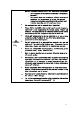
1.4 Safety warning information In order to ensure the safety of the patient and the operator, the following safety rules should be strictly observed in the use of the wireless ultrasonic probe. DANGER: 1. Do not disassemble the ultrasonic probe, which may cause electric shock. 2. Use the power cord supplied with this unit; use only the power supply provided by the company to supply power, the use of other specific power supply (such as UPS, etc.
1. Matters needing attention in clinical examination technology: CAREF UL: This equipment can only be operated by qualified medical personnel. This manual does not introduce a clinical examination technique. It is necessary to select the correct inspection techniques according to the professional training knowledge and clinical experience. 2. The equipment can not be checked for a long time. 3.
1 In order to prevent abnormal probe function, read the following safety precautions: After each ultrasonic examination, the ultrasonic coupling agent on the surface of the probe should be thoroughly erased. Otherwise, the ultrasonic coupling agent will be solidified on the probe head, which will affect the quality of the ultrasound image.
2 Product overview 2.1Intended use It is mainly used for pregnancy diagnosis of animals such as dogs, cats, equines, bovines, ovines; disease diagnosis of animal digestive system, urinary system and reproductive system; animal abdomen (liver, gallbladder, spleen, pancreas, gastrointestinal), kidney, urinary system ( Ultrasound examination of the bladder, ureter, gynecology (uterus, ovary), obstetrics (follicles, fetuses). 2.
software security procedures, no need to download; if the original system does not have its own security software, it is recommended to download some of the top anti-virus software to ensure system software security. Antivirus frequency It is recommended to perform anti-virus once a week to protect the system. 2.3.4 Power condition Charging port power input:DC 5V,2A 2.3.
Transport: 1. Do not use or store the system outside the specified environmental conditions. Working: 1. Please ensure that the use of the equipment to master a solid, otherwise, equipment may hurt the patient fall. 2. To ensure that the equipment in a dry environment, the operation of environmental temperature and humidity changes, may lead to liquid condensation in the circuit board, there is the risk of short circuit. WAR NING: 3.
2.4 system configuration The system is mainly composed of host equipment, probe and application(Android platform ) The configurable probe model is:C5-2Sv(Convex array),C5-2v(Convex array),L11-4v(Linear array),L11-4Sv(Linear array),C8-5v(Micro-Convex array) and E10-4v(Endocavitary array) 2.4.1 Standard configuration Main unit: 1 set Appendix: Application Operation manual 2.4.2 Components 2.4.2.
2.5 Symbol description This device uses the following symbol identification, the following list shows its meaning. Serial number Symbol Explain 1 Type BF application part explain:All ultrasonic probes are part of the BF application.
2.
2.7 Control panel Serial number Button icon Key name Function 1 Power switch / freeze / thaw button 2 (Gain) “+”button Gain increase 3 (Gain) “-”button Gain reductio 4 Main menu button 1、 Long press: one key optimization Press short: toggle image mod 5 (Depth) “ ”button Depth increase 6 (Depth) “ ”button Depth reduction 1, long press: power off 2, press: power on / freeze / thaw image 2.8 Basic interface 2.8.
2.8.1 Interface layout diagram Status and information display area The status and information display area includes system menu, WiFi/USB connection sign, patient information management, probe type, inspection type, puncture line, battery charge and system time. System menu Contains pre-set, version information, operation manual. WiFi/USB connection sign Displays the current probe connection.
Color mode,Click to enter Color mode, click again to enter Power mode; PW mode,Click to enter the pre-startup statu of PW mode and click again to start / pause to get the map.It's the same as update. Drop-down menu flag, click to enter the corresponding image mode of all parameters adjustment. Image parameter adjusting pulley:Slide up and down or click on the pulley to adjust the corresponding parameters. Function shortcut key area Contains freeze / active buttons and saves image button icons.
2.9 Information security 2.9.1 Forget password When the user forgets the password, the software can be reinstalled. At this time, the original password is cleared and a new password can be set. 2.9.
One grid is always bright (right) 10%~50% of electricity Slow flash 10% or less 23
3 Basic introduction 3.1 Working power supply WF-1v Veterinarian Pocket Ultrasound System does not work when external Power supply is connected. Connect to the Type-C interface of the probe by the charging power cord as required by the standard. The external power supply system of WF-1v Veterinarian Pocket Ultrasound System must meet the following requirements: Output:5V 2A DC internal electric source :7.
2. ING: CAR EFUL: When handling the probe head, make sure that the probe is closed or frozen In order to ensure the safety of the probe, work effectively, the need for daily inspection. Once the check to the abnormal situation, should immediately close the probe and contact with the service representative. If the probe will cause abnormal use of examination results is not accurate and even harm the patient and damage the probe itself.
After ultrasonic examination, the ultrasonic coupling agent on the surface of the probe should be completely erased. Otherwise, the coupling agent will be solidified on the probe head and affect the quality of the ultrasonic image Before and after each ultrasonic examination, the probe should be cleaned and disinfected. 3.2.3 Loading and unloading the probe Be sure that the probe is in a closed state, the head of the loading and unloading operations.
4 Detailed operation introduction 4.1 Image mode mode explain 【B】 Click to enter B mode. 【M】 Click to enter M mode. 【Color】 Click to enter Color mode.。 【Power】 Click to enter Power mode. 【PW】 Click to enter PW mode. 4.2 Image parameter adjustment Before adjusting the image parameters to optimize the image, adjust the brightness of the display so that it works best.
4.3 Parameter adjustment about B mode The B mode is the most basic imaging mode, and the intensity of the echo signal of a fault interface in the body is displayed by the light spot brightness and dark. The two-dimensional image of the animal soft tissue organ of the moving body is displayed in real time, and the organ morphology, the anatomical level and the adjacent relation can be clearly observed. 4.3.
Effect Auto-adjust optimized image. TGC Resume The attenuation caused by increasing tissue depth is compensated and the depth gain is adjusted in a piecewise manner. Effect By adjusting the signal gain in a specific depth range, the echo of the tissue image is uniform. Frequency Resume The emission frequency of the probe can be selected by fundamental frequency or harmonic frequency. The frequency value is displayed in real time on the image parameter area on the left side of the screen.
Effect The penetration and resolution near the focal point are higher than those outside the focus. Effect Resume Adjust the black and white grayscale contrast to optimize the image. Effect This function is effective for real-time, frozen and movie playback images. QBeam Resume The image is optimized by merging multiple frames from different deflection angles into a single frame.
Pseudo-color map Resume Color difference is used instead of gray difference to image, that is, grayscale map colorization. Effect WF-1v Veterinarian Pocket Ultrasound System provides four different pseudo-color maps, which are effective for real-time, frozen and movie playback images. 4.
4.4.2 M mode image optimization Gain Resume Adjust the gain of M mode ,displays in real time on the image parameter area on the left side of the screen. Effect By increasing the brightness of the gain image, more echo signals can be observed, but at the same time, there will be more noise.。 Depth Resume For adjusting the depth of the image display, the range of image depth can be adjusted by different probes.
Pseudo-color map Resume Color difference is used instead of gray difference to image, that is, grayscale map colorization. Effect WF-1v Veterinarian Pocket Ultrasound System provides four different pseudo-color maps, which are effective for real-time, frozen and movie playback images. Effect Resume Adjust the black-and-white gray-scale contrast to optimize the image. Effect WF-1v Veterinarian Pocket Ultrasound System provides 18 effects, and is effective for real-time, frozen and cine-played images.
4.5 Parameter adjustment about Color mode Color Doppler is used to observe the color blood flow and provide the flow direction and velocity information of the blood flow. In general, red indicates the blood flow to the probe, blue indicates the blood flow away from the probe, the brighter the color, the faster the blood flow, the darker the color, and the slower the blood flow rate. WARNING 1. : Color Doppler flow can only be used as a reference for doctors and can not be diagnosed directly.
Velocity Resume Showing the velocity range of blood flow, for this product, is actually regulating the measurable range of blood flow velocity. Effect After adjustment, the color blood flow image can be displayed more clearly and accurately. A lower velocity range should be used to measure low velocity blood flow, and a higher velocity range should be used to measure high speed blood flow. Influence Aliasing is easy to occur when measuring high-speed blood flow using a lower velocity range.
Map Resume Color image display effect parameters, according to the need to switch different map can get more comprehensive blood flow information. Influence This function is effective for real-time, frozen and movie playback images. Overturn Resume Set the display mode of Color mode, turn over the color ruler when it is turned on, and change the display mode of blood flow on the image. Influence This function is effective for real-time, frozen and movie playback images. A.
Adjustment method Parameter term Control panel adjustment Gain, depth SoftKey adjustment Velocity, Frequency, Color first, dynamic range, map, Wall filter, Sound Power, afterglow The Power mode shares the probe sound power of the B mode ,When the acoustic power is adjusted, the sound power of the two imaging modes changes synchronously.
Effect Changing the incident direction of the acoustic beam in color mode, thus changing the angle between the acoustic beam and the direction of blood flow, is only effective for the linear array probe. 4.7 Parameter adjustment about PW mode PW mode (spectral Doppler mode) is used to provide the information of blood flow direction and velocity. The transverse axis of the spectrum pattern represents the time and the longitudinal axis indicates the Doppler frequency shift.
Speed Resume Showing the velocity range of the blood flow, for this product, is actually a regulation of the speed. The speed value is displayed in real time in the image parameter area on the left side of the screen. Effect The color blood flow image can be displayed more clearly and accurately after adjustment. A lower velocity range should be used to measure low velocity blood flow, and a higher velocity range should be used to measure high speed blood flow.
SV Resume Adjusting the position and width of the pulse Doppler sampling volume gate, the current SV value is displayed in real time in the image parameter area on the left side of the screen. Effect When the sampling gate is small, the obtained result is more accurate, and when the sampling gate is large, the information range obtained is larger.
Effect The louder power increases the overall brightness of the image evenly, and the detection depth also increases. Influence In clinical application, proper sound power should be selected according to the actual situation and ALARA sound power principle. Frequency Resume Switching the probe frequency in Doppler mode, the frequency value is displayed in the image parameter area on the left side of the screen in real time.
5 Measure The operation of measurement can be divided into conventional measurement and applied special measuring package. 1. CAREFUL: 2. 3. 4. 5.1 All unsaved data will be lost by shutting down during the measurement process. During the measurement process, all measurement information on the image will be deleted and the conventional measurement data will be lost once the frozen state is lifted. A change in mode clears the conventional / applied special measurement data on the screen.
5.1.2 Conventional measure in M mode M mode measurements are as follows: Measure item Distance Time Function Measure the distance between any two points on a vertical line at a given time. Measure the time interval between two points on the M image. Gradient The average slope between two points is calculated by measuring the distance and time of the two points. Heart rate On M cardiogram, the interval between two cardiac cycles was measured and the heart rate was calculated. 5.1.
6 Cineloop/annotation/body mark During image scanning, freeze the image by pressing the freeze key. After the image freezes, the probe stops the sound output, leaving all images and image parameters unchanged. Image freeze state, press the freeze key will thaw the image, the system continues to scan the image. 6.1 Cineloop After the image freezes, the system supports movie playback and editing functions.
7 Probe 7.1 Probe description 7.1.1 Probe type L-Linear array probe; C-Convex array probe; E-Cavity probe. 7.1.2 Probe composition The probe is composed of piezoelectric ceramic wafer, acoustic focusing lens, shell and so on. 7.1.3 Probe performance index The performance indicators of each probe are published as follows: Table 1 Image performance Indexes Mode Order Project number A Probe nominal frequency (MHz) Probe model C5-2Sv C5-2v L11-4v L11-4Sv 3.5 3.5 7.5 7.
Mode Order Probe model Project number C5-2Sv C5-2v L11-4v L11-4Sv ≤10 ≤10 ≤5 ≤10 ≤10 ≤10 ≤5 ≤5 ≤±15 ≤±15 ≤±15 ≤±15 ≤10 ≤10 ≤10 ≤10 Transverse H geometric position precision(%) Longitudinal I geometric position precision(%) Perimeter and J area measurement deviation(%) M K mode time display deviation(%) Color L Service frequency (MHz) 2.0 3.5 2.5 3.5 6.0 7.5 6.0 7.
Mode Order number S Probe model Project C5-2Sv C5-2v L11-4v L11-4Sv Near the wall of the Near the wall of the Near the wall of Near the wall of Accuracy of pipe, no velocity pipe, no velocity the pipe, no the pipe, no position of indication; center of indication; center of velocity velocity Vernier in pipe, maximum pipe, maximum indication; indication; center Doppler sampling velocity display velocity display center of pipe, of pipe, maximum maximum velocity display veloc
Order Mode number Color L M Probe model Project Service frequency (MHz) E10-4v 5.0 Depth of investigation (mm) C8-5v 6.0 5.0 6.0 ≥40 ≥40 coincide coincide Relationship between color blood N flow image and gray-scale image of the pipe in which it is located Blood flow O direction requirement P Q Service frequency (MHz) It can be correctly identified It can be correctly identified and there and there is no aliasing. is no aliasing. 5.0 Depth of investigation(mm) 6.0 5.0 6.
1.In the protective sleeve or inside the probe surface coated with an appropriate amount of coupling agent, without the use of coupling agent, the image is not clear. 2.To probe into the protective sleeve to ensure the sterility of the probe. The protective sleeve of the tension to remove wrinkles and bubbles, do not pull too far. 3.With the rope to ensure the protection of security. 4.Check the protective sleeve to ensure no damage 7.3 Inspection and maintenance 7.3.
7.4 Cleaning and disinfection Probe into direct contact with the patient's components, in order to avoid infection, when a closed detection, ultrasonic detection system, please according to the requirements of the probe cleaning and disinfection (sterilization). Waring : 1 . 2 . 3 . 4 . Probe non-immersion equipment, Not recommended for underwater use. It is forbidden to immerse the probe plug in a liquid such as water or an anti - virus solution.Immersion can cause shock or failure.
Be careful : 1 The probe must be cleaned after each use; . 2 Do not use surgical brush to clean the probe, even if the use of soft . brush may damage the probe, only use a soft cloth; WARNIN G: 1 . 2 . 3 . 4 . 5 . The product must be away from machine with high current or strong magnetic. Do not immerse the probe in any type of liquid or detergent. Probe is strictly prohibited from immersing by any type of liquid. The method of disinfecting probe with gas or heating is strictly prohibited.
8 Puncture guide 8.1 Enter or exit puncture mode Under the Windows platform, in the SoftKey area, click B mode [Image Parameter Settings], and select [puncture (on / off)]. Set [Piercing frame model] for quick calibration. Set [guide line], depending on needle selection, A, B, and ALL. Set [linetype], have thick, medium, thin. WAR NING: 1. The guide leads must be calibrated before each puncture. 2. The frozen is not allowed at the time of puncture. 3.
9 Acoustic output description The contents of this chapter for the entire system (including host, probe, accessories and peripherals), in order to provide relevant information to the operator output sound and how to use ALARA control principle of irradiation time and other important safety information. In addition, this chapter also includes information related to the system of acoustic output real-time display. Please read this chapter carefully before use. 9.
Not all of the examinations can be output by ultrasonic low energy ultrasonic can be completed. Very low energy will only lead to low quality images or weak Doppler signal, thus affecting the reliability of diagnosis. However, the use of sound power is greater than the actual needs but also help to improve the quality of information for the diagnosis, but will increase the risk of biological effects.
CMI = 1 (MPa / MHz ) When the frequency is 1 MHz and the peak pressure is 1 MPa, the MI value is 1 MI can be considered as a threshold for cavitation. When gas and soft tissue exist at the same time to set the MI value to the low value. TI (Thermal index) : TI is determined by the total acoustic power and the tissue temperature rise of 1 degrees Celsius required sound power ratio.
9.5 Sound power setting Acoustic output regulation According to the bottom of the screen menu area [soft sound power] project regulating sound power. Regulation at the same time, the soft menu item and the middle of the screen will display the sound power offset position size. Numerical sound power level is big, said the sound output of current energy increases. In the frozen state of the image, the ultrasonic energy is not output.
9.6 Acoustic power control Sound output depends on the system operator, the operator should obtain qualified under the premise of effective diagnostic image to reduce the acoustic output. There are three types of operation control and sound output control: direct control and indirect control and receiver control. Direct control The system of direct control of acoustic output through the soft menu area [] sound power project adjusting acoustic output size.
I atten I water 10(-0.3 / 10 f c z ) Among them, Iatten is the attenuation of sound intensity, Iwater is in the tank the measured sound intensity (at a distance z), fc is the center frequency of the ultrasonic (measured in water), and Z is the distance apart. The attenuation value of pressure probe formula is similar, but the attenuation coefficient is 0.15 dB/cm/MHz, half of the sound strong.
Mechanical index is used to represent the mechanical effect (cavitation) the possibility of.MI depends on the attenuation of peak pressure and the center frequency, the actual peak negative pressure by the actual attenuation effect, which is caused by the actual attenuation between the probe and the focus of the organization. The organization of all animal solid attenuation is higher than 0.
temperature was measured under two conditions: transducer suspension in the absence of air circulation environment (Still Air) and probe contact phantom (Method B). The maximum surface temperature and maximum temperature rise of the transducer are listed below: Final Radiating Surface temp.(TF) and/or Temp.Rise(TR) (°C) Transducer test method Operation mode Ambient (°C) Initial temper ature (°C) C5-2Sv TMM Normal(B +C+PW) 25.554 25.261 TF=30.020 TR=4.759 C5-2Sv Still Air Normal(B +C+PW) 24.
WARN ING: 1、The use of inappropriate accessories will reduce the performance of the product. 2 、 The selected adapter should meet the requirements of the IEC60601-1-2: 2007 AC:2010 3、The equipment or system may be interfered with by other equipment even if it meets the emission requirements of the corresponding national standards. Cable information table Order Name Cable length(m) number Whether to Remarks shield or not 1 DC input power cord 1.5 yes / 2 C5-2Sv Probe cable 1.
8. Frequency band of emission:2412MHz~2470MHz Modulation type:DSSS modulate/OFDM modulate Frequency characteristic:802.11a/802.11b/802.11g Effective radiated power: 1 TX power: — 18.0dBm@1DSSS — 14.5dBm@54OFDM RX sensitivity — -95.7dBm@1DSSS — -74.0dBm@54OFDM The guide and manufacturer's statement are detailed in the following table.
Table 2: Electromagnetic disturbance guidance and manufacturer statement This system can be used in a specified electromagnetic environment, users should ensure the use of electromagnetic environment in the following provisions. Electromagnetic Immunity test IEC 60601Test level Accord level environment - A Guide The ground must be made of wood, concrete or tile.
Table 3: Electromagnetic disturbance guidance and manufacturer statement This system can be used in a specified electromagnetic environment, users should ensure the use in the electromagnetic environment in the following provisions.
Be careful 1: In 80MHz-800MHz, using a higher frequency formula Be careful 2: These guidelines do not apply in all cases. The material structure, objects and people can absorb and reflect electromagnetic waves, thus affecting the electromagnetic propagation a The radio base station (cellular and wireless) and ground mobile radio mobile phone antenna, receiver, field FM and am radio as well as TV broadcast is unable to use pure theory to accurately estimate.
If the rated maximum output power of the transmitter is not included in the values given above, can be estimated by using the corresponding column isolation distance equation. In the equation P is the nominal maximum output power of transmitter manufacturers are given, measured in watts. If the system image severely disturbed affect diagnosis, it is necessary to set the device away from the noise source or install the external RF transmission power noise filter the noise reduced to an acceptable level.
Appendix A Names and contents of toxic and hazardous substances or elements Table:Names and contents of toxic and hazardous substances or elements Toxic or hazardous substances or elements Toxic or hazardous substances or elements Six valence chromium (PBB) Two phenyl ether (PBDE) lead(Pb) mercury (Hg) cadmium (Cd) Six valence chromium (Cr(VI)) Internal wire rod × ○ ○ ○ ○ ○ LCD ○ ○ ○ ○ ○ ○ key/knob ○ ○ ○ ○ ○ ○ Shell(Plasti c cement) ○ ○ ○ ○ ○ ○ Shield ○ ○ × × ○ ○ PC
Izpta, α(z) Decay time space peak time average sound intensity MI Mechanical index P output power Pα Output power after attenuation P1 Bounded output power pi Pulse sound pressure square integral pr Peak sparse sound pressure pr.
Probe :C5-2Sv Mode:B 69
Probe:C5-2Sv Mode:B+M 70
Probe:C5-2Sv Mode:B+C Probe:C5-2Sv Mode:PW 71
Probe:C5-2Sv Mode:B+P 72
Probe:C5-2v Mode:B Probe:C5-2v Mode:B+M 73
Probe:C5-2v Mode:B+C Probe:C5-2v Mode:B+P 74
Probe:C5-2v Mode:PW Probe:L11-4v Mode:B 75
Probe:L11-4v Mode:B+M Probe:L11-4v Mode:B+C 76
Probe:L11-4v Mode:B+P Probe:L11-4v Mode:PW 77
Probe:L11-4Sv Probe:L11-4Sv Mode:B Mode:B+M 78
Probe:L11-4Sv Probe:L11-4Sv Mode:B+C Mode:B+P 79
Probe:L11-4Sv Mode:PW Probe:C8-5v Mode:B 80
Probe:C8-5v Mode:B+M Probe:C8-5v Mode:B+C 81
Probe:C8-5v Probe:C8-5v Mode:B+P Mode:PW 82
Probe:E10-4v Mode:B Probe:E10-4v Mode:B+M 83
Probe:E10-4v Mode:B+C Probe:E10-4v Mode:B+P 84
Probe:E10-4v Mode:PW FCC Statement This equipment has been tested and found to comply with the limits for a Class B digital device, pursuant to Part 15 of the FCC Rules. These limits are designed to provide reasonable protection against harmful interference in a residential installation. This equipment generates uses and can radiate radio frequency energy and, if not installed and used in accordance with the instructions, may cause harmful interference to radio communications.