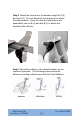
Step 2: Attach the claw arm to the bracket using bolt A (2) and nut A (2). The nut should be facing away from where the dish would be. Once the claw arm and bracket are assembled, use nut B (4) and bolt B (4) to attach the bracket to the reflector. Step 3: Mount the reflector in the desired location on the customer’s premise. The following pictures show the different mounting methods used with the Claw Reflector. 2000 Sunset Rd Lake Point, UT 84074 [2] Tel: 435.837.
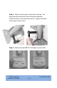
Step 4: Make sure the pipe on the base is plumb. The pipe from the bend to the top of the pipe should be vertical (shown in the previous picture). Tighten the bolts at the base of the mount. Step 5: Attach included WB FCC ID label to back of SM. 2000 Sunset Rd Lake Point, UT 84074 [3] Tel: 435.837.
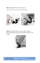
Step 6: Snap the SM into the Claw mount. *Note: Press the tab on the claw mount to release the SM. Step 6a: Slide the reflector over the mount. Once the azimuth adjustment has been made, tighten the bolts on the bracket. 2000 Sunset Rd Lake Point, UT 84074 Tel: 435.837.
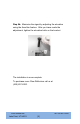
Step 6b: Maximize the signal by adjusting the elevation using the AccuAim feature. After you have made the adjustment, tighten the elevation bolts on the bracket. The installation is now complete. To purchase more Claw Reflectors call us at (435) 837-6200. 2000 Sunset Rd Lake Point, UT 84074 Tel: 435.837.
Exposure Separation Distances To protect from overexposure to RF energy, install PMP450SM radios so as to provide and maintain the minimum separation distances from all persons. Exposure Separation Distances Module Type Separation Distance from Persons PMP450SM At least 20 cm (approx 8 in) Details of Exposure Separation Distances Calculations and Power Compliance Margins Limits and guidelines for RF exposure come from: US FCC limits for the general population. See the FCC web site at http://www.fcc.
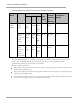
Exposure Separation Distances Calculated Exposure Distances and Power Compliance Margins Freq. Band Antenna 5.7 GHz OFDM Variable d Recommended Separati on Distance Power Compliance Margin P G S (calc ulated) Integrated, 9 dBi patch 0.079 W (19 dBm) .08 W (9 dBi) 10 W/m2 8 cm 20 cm (8 in) 8 Integrated, 9 dBi patch with 12 dBi Stinger 0.079 W (19 dBm) .126 W (21 dBi) 10 W/m2 28 cm 50 cm (20 in) 3.1 Integrated, 0.079 W 9 dBi (19 patch with dBm) 22 dBi Reflector Dish w/COP 1.