
User's Manual
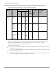
Table Of Contents

Exposure Separation Distances
Calculated Exposure Distances and Power Compliance Margins
Freq.
Band
Antenna
Variable
d
(calc
u-
lated)
Recom-
mended
Separati
on
Distance
Power
Compliance
Margin
P
G
S
5.7
GHz
OFDM
Integrated,
9 dBi
patch
0.079 W
(19
dBm)
.08 W
(9 dBi)
10
W/m
2
or 1
mW/c
m
2
8 cm
20 cm
(8 in)
8
Integrated,
9 dBi
patch with
12 dBi
Stinger
0.079 W
(19
dBm)
.126 W
(21
dBi)
10
W/m
2
or 1
mW/c
m
2
28 cm
50 cm (20
in)
3.1
Integrated,
9 dBi
patch with
22 dBi
Reflector
Dish w/COP
0.079 W
(19
dBm)
1.26 W
(31
dBi)
10
W/m
2
or 1
mW/c
m
2
89 cm
150 cm
(60 in)
2.8
The ―Recommended Distances‖ are chosen to give significant compliance margin in all cases. They are also
chosen so that an OFDM module has the same exposure distance as a Canopy module, to simplify
communicating and heeding exposure distances in the field.
These are conservative distances:
They are along the beam direction (the direction of greatest energy). Exposure to the sides and back of the
module will be significantly less.
They meet sustained exposure limits for the general population (not just short term occupational exposure
limits), with considerable margin.
The calculated compliance distance d is overestimated because the far-field equation models the antenna as
a point source and neglects the physical dimension of the antenna.