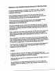
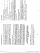
Addendum to the Operating Instruction Manual for CM Plus Radio: An audio-processing feature is included in the CM Plus radio — The Audio Com pander system that will be marketed under the name of “Clear Drive” or «Clear Drive Technology”. When activated, the radio will compress the audio level picked up by the microphone before it transmit over the air. The audio gain for high level peaks are compressed while the gain for low level signals are boosted.
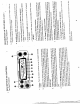
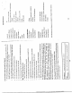
ALIGNMENT PROCEDURE 1) PHASE LOOKED LOOP AND CPU SECTION STEP | SETTING CONNECTION ADJUST [ADJUST FOR 1 Frequency adjustment ; Frequency counter CT901 3.6MHz £100Hz Mode : Receive to output pippin of Volume : Optional Squelch : Optional (Figure-1) CH Selector : 1 2 CPU Voltage check ; Connect DC vomit.
Second harmonic check ; Connect RF power At no modulation, Mode : Transmit meter with dummy Compare the level Volume : Optional oad to spectrum of fundamental Squelch : Optional analyzer through freq-spectrum to CH Selector : 19 attn, the level of to EXT-ANT. jack harmonic freq-ape on the set plectrum. (Figure-5). Suppression of the 2nd harmonic Freq. level must be lower than -60dB.
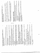
TEST EQUIPMENT SET-UP D.C Power Surplus freq. counter PRY Pin Set GND _r =O [FIGURE 1] Pin of CON D.C Power Supply DC Voltmeter Set AER TN Wood [FIGURE 2] Base of Q18 D.C Power Supply \ [ TT Oscilloscope ol [x Set b nn o GND O AO O {FIGURE 3} 16
RF Paymaster dummy load(50 Ohm Ol Sat entente Jack Fmt O = Dummy load {50 ohm 20 6B} DC Power Supply [FIGURE 4] RF Parameter 2008 ATT Enumerator | |X Set Couplet I= 5448 Antenna joc! DC Power Supply [FIGURE 5] RF Empowerment Antenna << jock —] O Couplet DC Power Supply Freq.
RF Power meter © D.C Power Supply = 2% Set Dummy load (58 owe Antenna jock Microphone jack at QE 5 Audio Gene rotor Modulation Meter [FIGURE 7] Standard Signal Generator 9 Set Sin adder Meter SSVYM o OY) D.
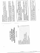
FCC ID: MGPCM-11 APPENDIX 7 CIRCUITS AND DEVICES TO STABILIZE FREQUENCY all 40 channels of transmitting, and receiving, frequencies are provided by PLL (Phase Locked Loop) circuitry. The purpose of the PLL is to provide a multiple number of frequencies from a VCO (Voltage Controlled Oscillator) with quartz crystal accuracy and stability locked to crystal oscillator reference frequency. The reference crystal oscillator frequency is 3.6 MHz.
FCC ID: MGPCM~1l APPENDIX 8 circuit ; : ; satiate The tuning circuit between the output of final amp Q603 and antenna, 4-stage "PH1: network T604, C607, C620, L604, C621, L602, C609, C605, C606, L605 serves as a spurious radiation suppressor. This network also serves to match the impedance between TX power amp and the antenna. AM Modulation Modulation signal from the mic amplifier (commander circuit is fed to the audio power amplifier IC401 via an RC audio filter network.