
User's Manual


Document Number 050-015-009R05
Wireless Mmatrix Proprietary and Confidential 13/20
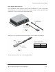
Connection Procedure
To operate and test this unit, a Power Supply Cable shown in fig.2 and a Serial Cable
will be needed.
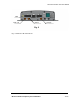
Connect the Serial cable terminated with a DB9 connector to a PC.
Connect the power supply cable to a 12V power supply (+12V wire and ignition wire
connected together). The power supply should be capable of handling at least 5A@
12V.
Please note that Communicator 1000C has internal super-capacitors, which
will cause the unit to take up to 1A for the first 20 seconds and then up to 5A
for 15 seconds at initial power up. After the super-caps are fully charged, the
current drops in receive mode under 400mA.
Use a serial modem interface like ZOC, HYPERTEMINAL or PROCOMM PLUS with the
following settings: 115200 baud, 8 bits, No parity, 1 stop bit, Flow Control: None.
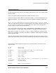
Note: Make sure that an antenna is always connected during transmit mode.
This is very important as the PA in the CDMA or the 802.11 cards might be damaged
without a proper load.
Once the Communicator 1000C is properly connected, turn the power supply on and
wait for the unit to boot-up. At the end of the boot-up sequence the user has to log in.
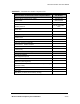
Communicator 1000C supports a large array of AT commands. Here are the more
common ones:
AT <CR> Return AT OK
AT &V Verbose mode
AT~NAMVAL?0 Display the modem phone number (e.g. 650-237-4000)
AT+GSN Get the ESN Number of the module
AT~PREV Protocol Revision
AT!RSSI? RSSI valued
AT+CSQ? Signal Quality
AT!PDS? Query Packet Data State: 1=> PPP connected. 0=> PPP inactive.
AT+CDV*22899 Activate modem
AT!STATUS Get Modem status
AT+CMIP? Mobile Station IP Address