4 4. Demobilization 4.1 Overview This chapter describes how to prepare (undeploy) the ground electronics for transport at the end of a project (demobilization). 4.2 Removing the WRU from the Field t This section describes the process to ready the WRU for movement to a new physical location or to remove it in preparation for demobilization.
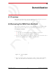
4. Demobilization ra f t Disassemble the WRU Figure 4–2 Undeployed Unit Optional: Remove batteries, antenna, or geophone as described in “Disassemble the WRU” on page 59. D 4 4.3 Disassemble the WRU This section describes the process to disassemble the WRU prior to demobilization. To disassemble the WRU: R00.e 1 Undeploy the equipment as described in “Removing the WRU from the Field” on page 58. 2 Remove the antenna from the unit. 3 Remove the geophone from the unit.
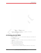
4. Demobilization Disassemble the WRU Continue to lift the lever using the bail to push the battery out of the connector. ra f t ● Figure 4–3 Removing the Battery Secure the equipment in the transport vehicle. D 5 60 RT System 2 v2.0.0 Deployment Guide © 2010-2012 Wireless Seismic, Inc. All rights reserved. R00.
5 5. Maintaining the Equipment In order to comply with FCC radio frequency (RF) exposure requirements, the RT System 2 units must be installed so that a minimum separation distance of 20 cm is maintained between the antenna(s) and the body of all persons at all times during normal operation.
6 6. Troubleshooting and Tips 6.1 Best Practices This section provides some tips on working with the equipment. 6.1.1 24 Ah Batteries t In order to maintain the best possible communication channel, observe the following tips: Place a fully charged 24 Ah battery on the backhaul every day. Keep extra 24 Ah batteries charged up at the staging area. Store 24 Ah batteries at the staging area when not in use. Deep discharging of the batteries can shorten their lifespan considerably. ra f 6.1.
. Troubleshooting and Tips Best Practices 6.1.5 Fiber Optic Cables D ra f t The fiber optic cables have an environmentally-sealed connector. See the following figure for an illustration of how the connectors work: Figure 6–1 Fiber Optic Cable Connector 6.1.6 Antennas When placing or selecting antennas in, consider the following: R00.e RT System 2 v2.0.0 Deployment Guide © 2010-2012 Wireless Seismic, Inc. All rights reserved.
6. Troubleshooting and Tips Troubleshooting In areas where there is a steep inclination, smaller gain antennas may provide a better signal. In areas where there is a steep inclination, try to reduce the inclination by going up or down at an angle rather than straight up or down. Use repeaters to cover overpass and steep inclination situations. If you need more signal strength, use an extender with a riser to elevate the antenna.
6. Troubleshooting and Tips Troubleshooting Table 6–1 Troubleshooting Fluidmesh Radios Problem Solutions Not communicating • • • Try sending a ping command in a CMD window to the IP address of the radio. If you are trying to connect directly with a computer, make sure you have configured a private network (see “Create a Private Network” on page 38).
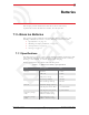
7 7. Batteries This chapter provides information about the batteries and battery requirements used in the Wireless Seismic, Inc. RT System 2. 7.1 Lithium Ion Batteries This section provides information regarding the characteristics, use, and handling of lithium ion batteries. See the following sections for details: “Specifications” on page 66 ● “Handling and Safety Guidelines” on page 67 ● “Transportation” on page 68 ra f t ● ● “Storage” on page 69 7.1.
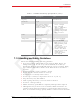
7. Batteries Lithium Ion Batteries Table 7–1 Lithium Ion Battery Specifications (cont.) Item Description Capacity Value 48.
7. Batteries Lithium Ion Batteries labeling, containment, and so on. Whenever possible the batteries must be discharged before disposal. Battery leads/contacts should be taped off to prevent accidental shorting. Each battery pack should be placed in a plastic bag. Recycling is encouraged when practical and applicable. The batteries contain recyclable material and are accepted by several battery recycling companies. Refer to one of the following for more information on recycling and disposal: ● http://www.
7. Batteries ra f t Lithium Ion Batteries Figure 7–1 Example Battery Shipping Label Batteries can be air shipped only if all of the following conditions are met: Box used meets the 1.2 m drop test box (“UN” rated box) for packaging Maximum weight of each package does not exceed 10 kg (22 lbs) Battery pack terminals are protected to prevent a short circuit Outer package is labeled with the current required label.
7. Batteries Charging Lithium Ion Batteries Remove the batteries from the WRU for storage The recommended storage temperature for Lithium ion batteries is as follows: From -20°C to +45°C for a maximum period of one month ● From -20°C to +35°C for a maximum of 6 months, after which time the battery packs will need to be recharged to above 50% capacity ● Storing at cooler temperatures slows down self discharge and capacity loss over time.
7. Batteries Charging Lithium Ion Batteries Do not continue recharging the battery if it does not recharge within the specified charging time. A lithium ion battery should NEVER be left unattended while charging. 7.2.2 Battery Charger The lithium ion battery charger is designed to operate from a single 10 A, 120 VAC service line. D ra f t The power supply to charge the battery pack is a 5VDC regulated voltage supply. Figure 7–2 Battery Charger R00.e RT System 2 v2.0.
7. Batteries LIU Battery ra f t Figure 7–3 Serial Number Label and LED Indicator 7.3 LIU Battery D TBD 72 RT System 2 v2.0.0 Deployment Guide © 2010-2012 Wireless Seismic, Inc. All rights reserved. R00.
8 8. Batteries Ce chapitre fournit des informations sur les batteries utilisées dans le système RT System 2 de Wireless Seismic, Inc. 8.1 Batteries au lithium-ion t Cette section fournit des informations sur les caractéristiques, l'utilisation et la manipulation des batteries au lithium-ion.
8. Batteries Batteries au lithium-ion Tableau 8–1 Spécifications des batteries au lithium-ion (cont.
8.
8.
8. Batteries Batteries au lithium-ion Les informations contenues dans le présent document ont pour but de fournir une connaissance générale des règlements s'appliquant aux batteries. Elles ne sont pas exhaustives, et les conditions mentionnées dans ce document peuvent avoir changées.
8. Batteries Chargement des batteries au lithium-ion Vérifier régulièrement l'état de charge de la batterie Envisager le remplacement de la batterie par une nouvelle en cas de constat d'une des conditions suivantes : ● L'autonomie de la batterie descend en dessous d'environ 80 % de son autonomie initiale ● Le temps de charge de la batterie augmente sensiblement 8.2 Chargement des batteries au lithium-ion Cette section décrit les précautions de chargement et présente le chargeur de batterie.
8. Batteries D ra f t Chargement des batteries au lithium-ion Exemple 8–2 Chargeur de batterie R00.e RT System 2 v2.0.0 Deployment Guide © 2010-2012 Wireless Seismic, Inc. All rights reserved.
8. Batteries LIU de batterie ra f t Exemple 8–3 Étiquette avec numéro de série et voyant DEL 8.3 LIU de batterie D TBD 80 RT System 2 v2.0.0 Deployment Guide © 2010-2012 Wireless Seismic, Inc. All rights reserved. R00.
A A. Legal Information A.1 FCC Rules and Regulations Compliance The Federal Communications Commission (FCC) regulates the use of antennas in the “Code of Federal Regulations – Title 47, Part 15 – Radio Frequency Devices, Subpart C – Intentional Radiators, Section 15.203 Antenna Requirement.” This equipment has been tested and found to comply with the limits for a Class A digital device, pursuant to part 15 of the FCC Rules.
A. Legal Information Industry Canada Compliance Table A–1 Antenna Specifications (cont.) Frequency (MHz) Model Gain Vertical Bandwidth Weight Dimension (Length x Diameter) WSI 65-0082 2400-2485 7.4 dBi 20º 5.4 oz 153 g 18.5 x 0.75 in 470 x 19 mm WSI 65-0131 2400-2485 4 dBi 50º 3.2 oz 90 g 8.7 x 0.
B B. l'information juridique B.1 Conformité avec les règles et règlements de la FCC La Federal Communications Commission (FCC) règlemente l'utilisation d'antennes dans l'article suivant : Code of Federal Regulations – Title 47, Part 15 – Radio Frequency Devices, Subpart C – Intentional Radiators, Section 15.203 Antenna Requirement. t Cet équipement a été testé et jugé conforme aux limites fixées pour un appareil numérique de classe A, conformément à la partie 15 des règles de la FCC.
B. l'information juridique Industrie Canada Conformité Tableau B–1 Spécifications des antennes (cont.) Fréquence (MHz) Modèle Gain Largeur de bande verticale Poids Dimensions (Longueur x Diamètre) 2400-2485 5 dBi 25º 0,5 lb 0,2 kg 12 x 0,6 po 355 x 15 mm WSI 65-0025 2400-2485 2 dBi à 2,4 120° 1,6 oz 45,4 g 7.
C C. Fluidmesh Radio Specifications The information in this chapter is reproduced here for your convenience from the Fluidmesh data sheet available at the following location: http://www.fluidmesh.com/press-room/product-literature/doc_details/160fluidmesh-mito-series © 2005-2010 Fluidmesh Networks, Inc. (90-0012) t C.
C. Fluidmesh Radio Specifications The Fluidmesh Mito Series transmitted. The overall result is a better, more reliable, multi-service wireless infrastructure. Compact Design for Easy Installation The Fluidmesh MITO Series has a compact form factor designed for low visual impact deployments. The integrated panel antenna makes for easy installation and supports a range of up to 30 miles in line of sight. The provided low-power POE injector guarantees a straight-forward set-up.
C. Fluidmesh Radio Specifications Fluidmesh 1100 with MITO Technology C.2 Fluidmesh 1100 with MITO Technology RADIO Frequency Bands: 5.15-5.25 and 5.725-5.825 GHz (US, FCC) 5.470-5.725 GHz (Europe, ETSI) 4.940 - 4.990 GHz (US,FCC) Modulation: OFDM (BPSK, QPSK, 16-QAM, 64-QAM) Modulation speed: Up to 300 Mbps TX Power: Up to 27 dBm, depending on configuration and regulatory constraints AX Sensitivity 5GHz: -96d8@6.5Mbps;-75dB@300Mbps Antenna Type: 2x2 MIMO Antenna Gain: 14.
C. Fluidmesh Radio Specifications Fluidmesh 3100 with MITO Technology OPTIONAL SOFTWARE PLUG-INS Ethernet Capacity Plug-in up to 1 Mbps (included) Ethernet Capacity Plug-in up to 2.5 Mbps Ethernet Capacity Plug-in up to 5 Mbps Ethernet Capacity Plug-in up to 10 Mbps Ethernet Capacity Plug-in up to 30 Mbps Ethernet Capacity Plug-in up to 60 Mbps Unlimited Wired Ethernet Capacity Plug-in (up to 100 Mbps) 802.1Q VLAN Support AES-128 Encryption RADIO Frequency Bands: 5.
C. Fluidmesh Radio Specifications MITO Series General Characteristics Storage Temperature: -30°C to +75°C Humidity: 95% condensing Weather Rating: IP65 Wind Survivability: 120 mph Shock & Vibration: ETSI 300-019-1.4 PHYSICAL Interfaces: One (1) Internal Ethernet 10/100BaseT autosensing, RJ45 Dimensions (mm): 370 (h) X 80 (w) X 70(d) Weight (Kg): 1.
C. Fluidmesh Radio Specifications MITO Series General Characteristics CEI! SUPPLIED ACCESSORIES PoE Injector with US/EU/UK Power Cord Pole Mounting Kit (i.e.Pole Mounting Kit Max O.D. 2 in.) WARRANTY Two (2) years on parts and labor Three (3) years optional extended warranty plan with advanced replacement Five (5) years optional extended warranty plan with advanced replacement ra f t Copyright © 2005-2010 Fluidmesh Networks, Inc. All rights reserved.
D D. LED Indicators This chapter provides the possible LED status and error indicators for WRUs and LIUs. Table D–1 5Mbps WRU Power On Sequence LED Indications LED Indicators Description Hard Reset The LEDs light up in clockwise rotation starting and ending with the A battery LED in the following cases: • When the batteries are attached • Anytime the unit resets itself • In between updating firmware applications D ra f t 1 Summary 2 RT System 2 v2.0.
D. LED Indicators Table D–1 5Mbps WRU Power On Sequence LED Indications (cont.
D. LED Indicators Once the power on sequence is complete, the LED indicators in the following table can be seen.
D. LED Indicators Table D–2 WRU LED Status Indications (cont.) Summary Description Geophone test in progress Flashing: • MODE • GEO Acquiring GPS fix Flashing: • MODE • GPS Neighbor discovery in progress Flashing: • MODE • RAD ra f t LED Indicators Flashing: • A • MODE • B Continue (lay flat to move to next test) Solid: • MODE • GEO • GPS NOTE: To skip a test during the self-test process, tilt the unit vertical (geophone down) until you see this triangle of LEDs.
D. LED Indicators You can skip a self-test by tipping the WRU geophone down and then returning it to the upright position (flat on the ground). Table D–3 WRU LED Error Indications Summary Description Single battery failure (B) A flashing Solid: • B • BAT Single battery failure (A) B flashing Solid: • A • BAT t LED Indicators Solid: • A • B • BAT ra f Both batteries failure Solid: • BAT • GEO • GPS • RAD Geophone failure GEO solid D Self test failure R00.
D. LED Indicators TBD Table D–4 LIU LED Discipline Indications Summary Description Disciplining to radio Flashing: • A • RAD Disciplining to GPS Flashing: • A • GPS A flashing ra f Disciplining t LED Indicators Flashing: • B • RAD Disciplined to GPS Flashing: • B • GPS D Disciplined to radio 96 Disciplined B flashing Incorrectly dropped out of cycle mode Flashing: • A • B • BAT • RAD RT System 2 v2.0.0 Deployment Guide © 2010-2012 Wireless Seismic, Inc. All rights reserved. R00.
D. LED Indicators Table D–4 LIU LED Discipline Indications (cont.) Summary Description Armed No lights D ra f t LED Indicators R00.e RT System 2 v2.0.0 Deployment Guide © 2010-2012 Wireless Seismic, Inc. All rights reserved.
E E. Weighted Mast This section describes the mast that uses weights to maintain stability. E.1 Specifications Tripod Weight = 50 lbs (22.73 kg) Minimum mast height = 53” (includes 6” for mounting) t Base size = 48” (1.2m) x 48” (1.2m) Supports up to 12 – 16” x 8” blocks ra f Pre-galvanized steel frame D Accepts up to 2.5” mast (not included) Figure E–1 Weighted Mast RT System 2 v2.0.0 98 © 2010-2012 Wireless Seismic, Inc. All rights reserved. Deployment Guide R00.
E. Weighted Mast Hardware Supplied E.2 Hardware Supplied The following hardware is supplied with the tripod mast: 4 - Bolt, Carriage 1/4 - 20 x 3/4" 12 - Bolt, Carriage 1/4 - 20 x 5/8" 4 - Bolt, 1/4 - 20 x 3/4" Hex Head 4- Bolt, 1/4 - 20 x 1/2" Hex Head 24-Nut, 1/4 - 20 24 - Lock washer, 1/4 Int. tooth t E.3 Assembly Instructions D ra f This section provides instructions and illustrations for assembly of the tripod.
E. Weighted Mast Assembly Instructions 4 Assemble the other end of the braces to the base frame using the four (4) 1/420 x 1/2" Hex Head Bolts, Lock washers, and Nuts. 5 Insert Bolts into upper and lower flange. 6 Slide the mast (not included) into position and tighten securely and weigh. Wade Antenna Ltd. D ra f t Ontario, Canada 100 RT System 2 v2.0.0 Deployment Guide © 2010-2012 Wireless Seismic, Inc. All rights reserved. R00.
Index Numerics Continue 94 CSS 23 192.168.0.10 30 2.4 GHz 23 4.9 GHz 30 5.1 GHz 30 5.
Index I I R Icon View 37 Industrial, Scientific, and Medical radio band 23 IP address Fluidmesh default 30 ISM 23 RAD 93 radio band 23 color 30 configure 38 datasheet 30 install two 53 kit 29 network configuration 38 radios 23 relay 23 remove battery 59 repeater 20 restore network settings 49 L LED status 91 LIU Armed 97 Disciplined 96 Disciplined to GPS 96 Disciplined to radio 96 Disciplining 96 Disciplining to GPS 96 Disciplining to radio 96 error 96 kit 26 t mast 98 erect 49 mast kit 33 masts 34 m
Index W W D ra f t Windows firewall 36 WRU 23 power off 58 power on 20 powers down 94 tests 21 R00.e RT System 2 v2.0.0 Deployment Guide © 2010-2012 Wireless Seismic, Inc. All rights reserved.