
Specifications


Page 6
WT1231H
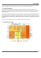
Figure 41. +20dBm Schematic
....................................................................................................................................
77
Figure 42. Package Outline Drawing
...........................................................................................................................
78
Index of Tables Page
Table 1. WT1231H Pinouts
..............................................................................................................................................
10
Table 2. Absolute Maximum Ratings
............................................................................................................................
11
Table 3. Operating Range
............................................................................................................................................
11
Table 4. Power Consumption Specification
..................................................................................................................
12
Table 5. Frequency Synthesizer Specification
..............................................................................................................
12
Table 6. Receiver Specification
....................................................................................................................................
13
Table 7. Transmitter Specification
................................................................................................................................
14
Table 8. Digital Specification
........................................................................................................................................
15
Table 9. Bit Rate Examples
..........................................................................................................................................
20
Table 10. Power Amplifier Mode Selection Truth Table
...............................................................................................
21
Table 11. High Power Settings
.....................................................................................................................................
22
Table 12. LNA Gain Settings
........................................................................................................................................
23
Table 13. Receiver Performance Summary
..................................................................................................................
25
Table 14. Available RxBw Settings
...............................................................................................................................
26
Table 15. Available DCC Cutoff Frequencies
...............................................................................................................
27
Table 16. Basic Transceiver Modes
.............................................................................................................................
35
Table 17. Range of Durations in Listen Mode
..............................................................................................................
39
Table 18. Signal Acceptance Criteria in Listen Mode
...................................................................................................
40
Table 19. End of Listen Cycle Actions
..........................................................................................................................
40
Table 20. Status of FIFO when Switching Between Different Modes of the Module
................................................... .
46
Table 21. DIO Mapping, Continuous Mode
..................................................................................................................
48
Table 22. DIO Mapping, Packet Mode
.........................................................................................................................
48
Table 23. Registers Summary
......................................................................................................................................
60
Table 24. Common Configuration Registers
.................................................................................................................
63
Table 25. Transmitter Registers
...................................................................................................................................
66
Table 26. Receiver Registers
.......................................................................................................................................
67
Table 27. IRQ and Pin Mapping Registers
...................................................................................................................
69
Table 28. Packet Engine Registers
..............................................................................................................................
71
Table 29. Temperature Sensor Registers
.....................................................................................................................
74
Table 30. Test Registers
..............................................................................................................................................
74
Table 31. Crystal Specification
.....................................................................................................................................
75