WT32-SC01 Datasheet Version V3.
Disclaimer and copyright notice Information in this article, Include URL for reference, subject to change without notice. The documents are provided "as is" without any warranty liability, including any warranties of merchantability, fitness for a particular purpose or non-infringement, and any warranties referred to elsewhere in any proposal, specification or sample. This document is not liable for any infringement of any patent rights arising from the use of the information in this document.
Content OVERVIEW ..................................................................................................................................................................... 1 BOARD SIZE ................................................................................................................................................................... 1 HARDWARE RESOURCE ....................................................................................................................................
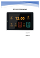
Overview WT32-SC01 is a development board for visual touch screen, the board is equipped with GUI platform firmware developed independently, support graphic drag and drop programming to help users complete the development of customized control platform. The main controller of WT32-SC01 development board adopts esp32-wrover-b module, this module is a general-purpose Wi Fi + Bt + ble MCU module, 4MB SPI flash and 8MB PSRAM are configured in.
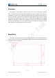
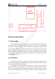
Figure 2-2:Physical dimension diagram 1 Figure 2-3:Physical dimension diagram 2 2/14 Wireless-Tag Technology Co., Limited http://www.wireless-tag.
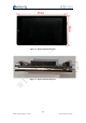
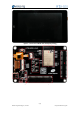
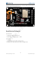
Hardware Resource The hardware resources of the development board are as follows: Figure 2 shows the physical front view of the development board. It consists of a 3.5-inch LCD screen with a resolution of 320x480 and a capacitive touch pad, and it Supports two touch. Figure 3 is the physical figure on the back of the development board, which contains the following hardware resources: 1、ESP32-WROVER-B Module Esp32-wrever-b is a Wi Fi + Bt + ble MCU module for all kinds of applications.
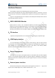
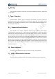
6、RST Key Touch the self-reset button to connect to the EN pin of ESP32. This button can be used to reset ESP32. 7、Type-C Interface Universal USB-C interface (Type-C interface), this interface is used to power the development board, UART communication and firmware download. The hardware of the download circuit implements data flow control, so the firmware download supports oneclick automatic download.
Figure 3-1: Front view of WT32-SC01 development board Figure 3-1: Rear view of WT32-SC01 development board 5/14 Wireless-Tag Technology Co., Limited http://www.wireless-tag.
Figure 3-3: WT32-SC01 board interface definition diagram Power On Instructions 1、Power supply This development board supports USB Type-C 5V power supply and reserved external power input interface (as shown by reference number 5 in Figure 3).
provides external expansion board. Figure 5 is a schematic diagram of the test points of the power supply of the development board. Figure 4-1: Schematic diagram of power supply test points of the development board Board Electrical Parameters Test environment: 1、Temperature: Room temperature 25 ℃ 2、Power supply: 5.0V Voltage ripple V < 100mA Test parameters: 1、Normal working current: 240mA(Average current) 2、Working current under sleep: Less than 18mA(Average current) 7/14 Wireless-Tag Technology Co.
Circuit Schematic Figure 6-1: Schematic diagram one Figure 6-2: Principle 2 8/14 Wireless-Tag Technology Co., Limited http://www.wireless-tag.
Figure 6-3: Schematic diagram three Schematic diagram 4 9/14 Wireless-Tag Technology Co., Limited http://www.wireless-tag.
Firmware Burning 1、Step One: Connect the WT32-SC01 board to the computer via the USB-TypeC data cable. Since this development board has automatic data flow control processing, the firmware can be automatically downloaded through ESP32 Flash_Download_Tools. 2、Step Two: As shown in Figure 7-1 below: Select the firmware path to be burned at 1. The address is usually 0X00.
Figure 7-1: Burning instructions 11/14 Wireless-Tag Technology Co., Limited http://www.wireless-tag.
Function Development 1、Screen Brightness Adjustment As shown in Figure 8-1, GPIO23 of ESP32 is a pin to control the LCD backlight, Users can control the backlight on and off through IO23 or adjust the backlight brightness of the LCD through PWM modulation. Figure 8-1: LCD backlight control diagram 12/14 Wireless-Tag Technology Co., Limited http://www.wireless-tag.
2、Graphical Interface Development Users can quickly develop through our online platform, the platform is similar to MIT APP Inventor, it realizes the rapid development of building blocks. At present, the platform has improved the development of graphical interface, more driver code blocks will be continuously improved in the future. The login URL of the online platform is as follows: http://esp32.8ms.xyz/login .
Figure 8-3: Platform development interface three 14/14 Wireless-Tag Technology Co., Limited http://www.wireless-tag.
Federal Communication Commission Statement (FCC, U.S.) This equipment has been tested and found to comply with the limits for a Class B digital device, pursuant to Part 15 of the FCC Rules. These limits are designed to provide reasonable protection against harmful interference in a residential installation. This equipment generates, uses and can radiate radio frequency energy and, if not installed and used in accordance with the instructions, may cause harmful interference to radio communications.
Information that must be placed in the end user manual: The OEM integrator has to be aware not to provide information to the end user regarding how to install or remove this RF module in the user's manual of the end product which integrates this module. The end user manual shall include all required regulatory information/warning as show in this manual.
Integration instructions for host product manufacturers according to KDB 996369 D03 OEM Manual v01 2.2 List of applicable FCC rules FCC Part 15 Subpart C 15.247 & 15.207 & 15.209 2.3 Specific operational use conditions The module is a Bluetooth module with WiFi & BR&EDR & BLE 2.4G function.
2.8 Label and compliance information Host product manufacturers need to provide a physical or e-label stating “Contains Transmitter Module FCC ID: 2AFOS-WT32-SC01” with their finished product. 2.