Wireless-Tag Technology Co., Ltd. V1.0.1 WT5010-S2 Datasheet V1.0.1 December 11, 2020 Wireless-Tag Technology Co., Ltd. ©2020 Wireless-Tag Technology Co., Ltd. All rights reserved. http://www.wireless-tag.
Wireless-Tag Technology Co., Ltd. V1.0.1 About this document This document provides users with WT5010-S2 specifications. Document version Please visit Wireless-Tag’s official website to download the latest version of the document. Revision history Please go to the document revision history page to view the revisions of the document. Disclaimer and copyright notice Information in this paper, including URL references, is subject to change without prior notice.
Wireless-Tag Technology Co., Ltd. V1.0.1 Document Revision History No. Version Changes Change (+ / -) description Author Date 1 V1.0.0 C First release Fiona Nov 17, 2020 2 V1.0.
Wireless-Tag Technology Co., Ltd. V1.0.1 Contents 1 Overview........................................................................................................................................................1 2 Chip Dimensions............................................................................................................................................3 3 Pin Definition.........................................................................................................................
Wireless-Tag Technology Co., Ltd. V1.0.1 1 Overview BLE5.0 / BLE5.1 Support 125Kbps/500Kbps/1Mbps Receiving sensitivity: -99.7dBm@1Mbps -105dBm@125Kbps Transmit power: +12 dBm(Max.) Link gain: 117dBm@125Kbps(Max.) Support Single-Ended Antenna Output BLE MESH Support BLE SIG Mesh Support private MESH MCU core 32-bit CPU core Frequency up to 64MHZ Max. 64KB Data SRAM memory Max.
Wireless-Tag Technology Co., Ltd. DMA: support 8 multiplex channels Watchdog timer: IWDG and WWDG Peripheral interconnection PIS System tick timer V1.0.
Wireless-Tag Technology Co., Ltd. V1.0.1 General-purpose IO 2 Chip Dimensions Figure 1 Chip Dimensions ©2020 Wireless-Tag Technology Co., Ltd. All rights reserved. http://www.wireless-tag.
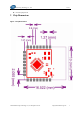
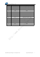
Wireless-Tag Technology Co., Ltd. V1.0.1 3 Pin Definition 3.1 Pin Layout Figure 2 Top View 3.2 Pin Description The module has a total of 24 pins. See Table 1 for specific descriptions. Table 1 Pin Definition Pin No. Pin Name Description 1 B12 GPIO/ADC Channel 0 2 B13 GPIO/ADC Channel 1 3 B14 4 B15 GPIO/Wake-up 5 A00 GPIO/ADC Channel 4/Wake-up 6 A01 GPIO/ADC Channel 5 GPIO (BOOT pin, high level is required when programming) ©2020 Wireless-Tag Technology Co., Ltd. All rights reserved.
Wireless-Tag Technology Co., Ltd. V1.0.1 Pin No. Pin Name Description 7 GND Module power negative 8 GND Module power negative 9 A02 GPIO/ADC Channel 6 10 A07 GPIO/Wake-up 11 A08 GPIO 12 A09 GPIO 13 A13 GPIO 14 A14 GPIO 15 A15 GPIO 16 B00 GPIO 17 VCC Module power positive 3.
Wireless-Tag Technology Co., Ltd. V1.0.1 4 Functional Description 4.1 Direct Memory Access Controller (DMA) The Direct memory access (DMA) is used to provide high-speed data transfer between peripheral and memory or between memory and memory, without intervention from CPU, data can be transferred quickly by DMA, which frees up CPU resources for other operations.
Wireless-Tag Technology Co., Ltd. V1.0.1 4.3 Window Watchdog(WWDG) Window Watchdog(WWDG)will generate a WWDG reset if it is refreshed too early or too late. It can be used to detect whether the software fails to refresh the watchdog or it refreshes the watchdog in the refresh prohibited area to prevent the program from running into an uncontrollable state.
Wireless-Tag Technology Co., Ltd. V1.0.1 Analog port Support reset/set of port output data, bitwise operation Support multiplexing as peripheral functions port Configurable output drive capacity: four drive capacity options Support 16 external input interrupts Support write protection of port configuration 4.5 Peripheral Interconnection PIS is used as a bridge interface for the interconnection of peripherals in the microcontroller.
Wireless-Tag Technology Co., Ltd. V1.0.
Wireless-Tag Technology Co., Ltd. V1.0.1 dead-time insertion). Pulse widths and waveform periods can be modulated from a few microseconds to several milliseconds using the timer Prescaler and the RCC clock controller Prescaler. The advanced-control timers (ADTIM), general-purpose timers (GPTIMA, GPTIMB, GPTIMC) and basic timers (BSTIM) are completely independent and do not share any clock sources. They can be synchronized together as well.
Wireless-Tag Technology Co., Ltd. V1.0.1 basic timers (BSTIM1) are completely independent and do not share any clock sources.
Wireless-Tag Technology Co., Ltd. V1.0.
Wireless-Tag Technology Co., Ltd. V1.0.1 The features are described as follows: Configurable conversion accuracy (6/8/10/12) Interrupt generation at the end of conversion, the end of injected conversion, analog watchdog or overrun events.
Wireless-Tag Technology Co., Ltd. V1.0.1 4.16 Inter-Integrated Circuit Interface(I2C) The I2C (Inter-chip) bus interface connects the microcontroller and the serial I2C bus. It provides the multi-master capability and controls all I2C bus-specified sequencing, protocol, arbitration and timing. It supports standard mode, fast mode and super ultra-fast mode. At the same time, it is compatible with SMBus (System Management Bus) and PMBus (Power Management Bus).
Wireless-Tag Technology Co., Ltd. V1.0.1 slave mode. LSSPI can be connected to any serial master or serial slave peripheral device using one of the following interfaces. The features are described as follows: Support SPI serial peripheral interface Support SSP protocol Support national semiconductor ray 4.18 Serial Peripheral Interface 2(SPI2) The SPI/I2S interface can be used to communicate with external devices based on the SPI protocol and the I2S audio protocol.
Wireless-Tag Technology Co., Ltd. Support SPI Motorola mode Hardware CRC can achieve reliable communication V1.0.1 CRC value can be transmitted as the last byte of TX mode CRC automatically performs an error check to the last received byte.
Wireless-Tag Technology Co., Ltd. V1.0.1 The UART offers a wide range of baud rates using a fractional baud rate generator. UART supports asynchronous communication and half-duplex single-wire communication. It also supports the LIN (local interconnection network), Smart Card Protocol and IrDA (infrared Data Association) SIR ENDEC specifications, and modem operations (CTSn/RTSn). It also supports multiprocessor communication.
Wireless-Tag Technology Co., Ltd. V1.0.
Wireless-Tag Technology Co., Ltd. V1.0.1 Federal Communication Commission Statement (FCC, U.S.) This equipment has been tested and found to comply with the limits for a Class B digital device, pursuant to Part 15 of the FCC Rules. These limits are designed to provide reasonable protection against harmful interference in a residential installation.
Wireless-Tag Technology Co., Ltd. V1.0.1 Validity of using the module certification: In the event that these conditions cannot be met (for example certain laptop configurations or co-location with another transmitter), then the FCC authorization for this module in combination with the host equipment is no longer considered valid and the FCC ID of the module cannot be used on the final product.
Wireless-Tag Technology Co., Ltd. V1.0.1 2.4 Limited module procedures Not applicable. 2.5 Trace antenna designs Not applicable. The module has its own antenna, and doesn’t need a host’s printed board microstrip trace antenna etc. 2.
Wireless-Tag Technology Co., Ltd. V1.0.1 according to the actual test modes for a stand-alone modular transmitter in a host, as well as for multiple simultaneously transmitting modules or other transmitters in a host product. Only when all the test results of test modes comply with FCC requirements, then the end product can be sold legally. 2.10 Additional testing, Part 15 Subpart B disclaimer The modular transmitter is only FCC authorized for FCC Part 15 Subpart C 15.247 & 15.207 & 15.