
Cut Sheet


BACK FEEDING FROM FLEXIBLE OR RIGID METAL CONDUIT
Cut hot, neutral and ground wires of V2400 Raceway Harness at location of raceway
base entrance knockout that will be removed. Remove 1/2" entrance knockout from
base and attach 1/2" feed connector (not supplied). Mount raceway base with
harness using No.10 Panhead screws. Connect harness to feed wires using one of
the approved methods shown above in Fig. 2A or Fig. 2B
Wiremold Electrical Systems conform to and should be
installed and properly grounded in compliance with
requirements of the current National Electrical Code, Canadian
Electrical Code or codes administered by local authorities.
All electrical products may represent possible shock or fire
hazard if improperly installed or used. Wiremold electrical
products are UL Listed to U.S. and Canadian safety
standards, made for interior use only, and should be installed
in conformance with current local and/or the National
Electrical Code.
1 No. V2400B Base section with grounding type receptacles rated 20A, 125V prewired with No. 12 type THHN conductors and
snapped into base.
1 No. 2400C Cover section
1 No. 2410 Coupling
2 No. V2410B Blank End Fittings
V2400 PLUGMOLD
®
RACEWAY AND MULTIOUTLET SYSTEM
INSTALLATION INSTRUCTIONS
Installation Instruction No.: 40063R2 – Updated July 2004
RECOMMENDED INSTALLATION STEPS:
1. Lay out raceway path on mounting surface.
2. Locate power feed point, then install raceway base & harness (See
instructions that follow).
3. Commence wiring according to instructions.
4. Install raceway covers. If any cuts are necessary, hold raceway
cover up against mounted raceway base/harness so that
receptacle holecuts match with receptacles. Mark cover and cut
5.Install fitting cover last over raceway covers (excluding 2410A
Entrance End Cover).
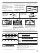
FEED METHODS:
Fig. 2A W30 METHOD
Fig. 2B WIRE NUT METHOD
W30 WIRE CONNECTORS… HOW TO USE
END FEEDING FROM FLEXIBLE OR RIGID METAL
CONDUIT (USING V2410A ENTRANCE END FITTING)
Mount V2400 Base and harness on surface with No.
10 Panhead screws.
Insert V2410A Entrance End Fitting base (available
separately) into end of V2400B Raceway Base.
Assemble 1/2" connector (not supplied) with V2410A
and bring in feed cable with wires extending at least 2
1/2" beyond connector.
Connect green conductor infeed which is connected
directly to the service grounding terminal using 2409
Ground Clamp, or equivalent approved method for
equipment grounding connections. Connect black and
white harness wires to black and white feed wires with
W30 Wire Connectors (available separately) inserting
only conductors of same color in a connector. See
“W30 Wire Connectors… How to Use”. DO NOT USE
W30 WIRE CONNECTORS WITH GROUND WIRES.
Any unused wire leads must be individually closed up
with a wire nut. DO NOT CONNECT UNUSED LEADS
TOGETHER.
Snap V2410A Fitting Cover onto raceway base. Cut
raceway cover to fit and snap onto raceway base.
NOTE: FOR EASE OF INSTALLATION AT CORNERS – Cut out any
receptacle within 4" of wall corner. This will allow sufficient space
within raceway for wire connections where two runs meet. Cut a blank
raceway cover piece to fit over any exposed area, if necessary.
NOTE: Units may be end-fed as in Step 1A through V2410A Entrance End Fittings or, back-fed as in 2A or
2B through 1/2" entrance knockouts in base.
Fig.1A
V2410A ENTRANCE
END FITTING
2 1/2"
V2400B
V2400B
Receptacles
V2400C
V2400B &
Harness
W30 pressure-type connectors
(available separately) are for common
connection of 2, 3, or 4 No. 12 or
No. 14 solid conductors.
NOT TO BE USED TO CONNECT GROUNDING CONDUCTORS.
Black
W30 Connector
White
V2400B
Wire Nut
Jumper
Ground
V2400B
Wire Nut
Black
White
Ground
Jumper