
Installation Manual

AL3300B BASE
AL3301 COUPLING
AL3309 GROUND CLAMP
AL3300 SYSTEM PRODUCT APPLICATION
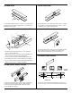
At AL3300B base section butt joints, slide AL3301 Coupling
into first base section. Mount next base to surface. Center
coupling on joint. Tighten locking screws.
To attach AL3300B Series base sections to mounting surface.
Drill 9/32" holes in the base (approx. 48" o.c.). Fasten base
with #8 flat head screws.
1. Provide electrical feed through 1/2" or 3/4" trade size
K.O.’s in at AL3310B1 end.
2. Attach base section to mounting surface by drilling 9/32"
holes in base then fastening with #8 flat head.
3. Secure conductors in place with AL3300WC Wire Clips.
4. Join additional raceway sections with AL3301 Coupling.
5. Close end with either AL3310B or AL3310B1 End Fitting.
6. Snap cover into base to complete installation.
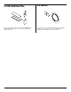
Position AL3309 Ground clamp into rib in AL3300B raceway
Base. Tighten locking screw. Attach ground wire using
brass cup washer and green hex nut to ground lug.
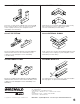
AL3300 SERIES DEVICE PLATES
AL3300D SERIES DIVIDER
For AL3346 and AL3356 Series Device Plates, install wiring
to devices as required. Attach device to plate using #6
screws and "keep" nuts (provided). Snap device plate
onto AL3300B raceway base.
Position AL3300D Divider into AL3300B raceway base as
shown. See cross sections below and refer to wire fill charts.
48"
[1219mm]
2
1
5
DIVIDER AND DIVIDER
CLIPS (OPTIONAL)
OPTIONAL
DIVIDER
SECTION A-A
DEVICE PLATE
A
A
B
B
C
C
SECTION B-B SECTION C-C
4
3
6