
Cut Sheet


2
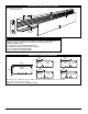
Raceway may be configured in single or multiple channels in several versatile ways to accommodate
power, data, or communications wiring.
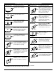
NOTE: Cross sectional area of each compartment indicated.
AL5200 Series Raceway Dimensions
2 3/16"
(56mm)
1 5/8"
(41mm)
2.85 sq. in.
(1838.7mm
2
)
5.50 sq. in.
(3548.38mm
2
)
3.90 sq. in.
(2516.12mm
2
)
1 5/8"
(41mm)
2.85 sq. in.
(1838.7mm
2
)
2.40 sq. in.
(1548.38mm
2
)
2.85 sq. in.
(1838.7mm
2
)
4.80 sq. in.
(3096.77mm
2
)
3.50 sq. in.
(2258.06mm
2
)
3 1/8"
(79.2mm)
2"
(51mm)
5"
(127mm)
8.50 sq. in.
(5483mm
2
)
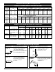
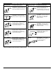
1 Provide electrical feed through 1/2" or 3/4" (12.7mm or 19.1mm) KOs in AL5210B2 End Cap.
2 Attach base section to mounting surface by drilling 9/32" (7.1mm) holes in the base,
and using #8 flathead screws.
3 Secure conductors in place with AL5200WC Wire Clip.
4
Join additional raceway sections with two AL5201
Couplings.
5 Close ends with AL5210B2 Blank End Fittings.
6 Snap cover into base to complete installation.
NOTE: Illustration is for showing
product applications only.
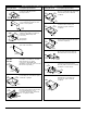
AL5200 Series Raceway System Layout
KEY
3
2
1
6
5
4
Snap-in Divider
(Optional)
4.50 sq. in.
(2900mm
2
)