
Installation Manual
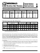


TELEPHONE CABLE-TYPE CM/CMR 24 AWG COAXIAL IBM CABLING
NUMBER OF PAIRS RG62A/U RG6/U RG59/U RG58A/U SYSTEM SIGNAL WIRE
CABLE TYPE 100 75 50 25 6 4 3 2 22 Gage 18 Gage 20 Gage 20 Gage Type 1 Type 2 18AWG 20 AWG 22 AWG 24 AWG
Nominal O.D. Inches 0.68 0.60 0.50 0.38 0.22 0.18 0.14 0.12 0.26 0.275 0.242 0.195 0.43 0.51 0.066 0.057 0.05 0.044
Capacity @ 30% XSA 6 8 11 20 59 88 146 199 42 38 49 75 16 11 658 882 1146 1480
Capacity of Divided
@ 30% XSA 3 4 6 10 29 44 72 98 21 19 24 37 8 5 325 435 566 730
Capacity @ 60% XSA 12 16 23 40 118 177 292 398 85 76 98 151 31 22 1316 1764 2293 2961
Capacity of Divided
@ 60% XSA 6 8 11 20 58 87 144 196 42 37 48 74 15 11 649 870 1131 1461
Installation
Instructions
S4000 Raceway Wire Fill Capacities for Power
POWER WIRING WITHOUT DEVICES WITH DEVICES
Wire Size (AWG) Non-Divided Divided Non-Divided Divided
(THHN/THWN) O.D. 40% Fill 40% Fill 40% Fill 40% Fill
2 0.388 25 13 12 5
4 0.328 35 18 16 7
6 0.257 58 29 26 11
8 0.218 80 40 37 15
10 0.153 163 81 74 30
12 0.122 257 127 117 48
14 0.105 347 171 158 64
S4000 Data/Communication Wire Fill Capacities
NOTES: 1) XSA = Cross Sectional Area of S4000 Surface Raceway.
2) Capacity range is calculated at 30% to 60% of raceway area as stated in the Commercial Building Standard for
Telecommunications Pathways and Spaces, EIA/TIA-569.
3) Reduce wirefill by 20% when fittings are to be used in installation.
All Wiremold electrical products, unless specifically noted, are listed by Underwriters’ Laboratories, Inc. and conform to U.S.
Federal Specification W-C-582. They comply with the National Electrical Code. Products designed primarily for use in tele-
phone or communications wiring and tools normally do not require U.L. Listing or CSA certification. Most products are CSA
certified in compliance with the Canadian Electrical Code. All products must be installed in a manner consistent with applic-
able electrical codes. Wiremold S4000 Stainless Steel Surface Raceway is CSA certified (File No. LR350) and listed by
Underwriters’ Laboratories (File Nos. E4376 [Raceway] and E41751 [Fittings]). This product is in compliance with the
National Electrical Code and the Canadian Electrical Code.
See typical basic system (illustrated on back) for installation details. In general, the following procedure for installing S4000
is recommended.
1. Starting at feed connection, install S4000 Base sections over entire run. Butt ends of sections and install couplings as
shown on back of this sheet. Cut base sections to length as required for connection of bases of fittings. Custom pre-
cut base and cover lengths are available and recommended to ensure an expeditious installation.
2. Assemble device brackets in S4000 Base.
3. Install wiring in base and wire devices.
4. Assemble devices and device covers in S4000 Base.
5. Cut S4000 Cover sections to length as necessary and snap onto base. It is recommended that covers overlap base
joint.
6. Tighten all fitting locking screws securely.
S4000 Stainless Steel Raceway
NOTES: 1) % Fill is based on use of Surge/GFCI style devices, mounted perpendicular in raceway.
2) Reduce wirefill by 20% when fittings are to be used in installation.