
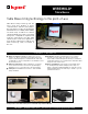
Specification Sheet


4
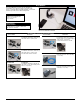
Design a Cord-Ended
TableSource Table Box
Sample Part: TSAM2H1IV2U
Design a Hard-Wired
TableSource Table Box
Sample Part: TSAP2Z1BK2UG
TableSource
™
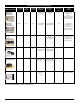
Table Boxes Configurator
IMPORTANT
Use this chart to configure
your own custom TableSource
activation. Many of the
configurations are standard
offerings, and can be quoted
and delivered to you quickly
with the help of our Wiremold
Customs group. Just call in with
your TableSource part number,
and they will be able to supply
you with a quote, technical
specifications and a CAD
Drawing.
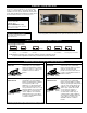
1. Select face for
mounting device.
Input letter.
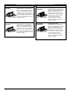
7. Choose number
of USB modules.
Input a number
followed by "U"
#U = Number of USB
Modules
2. Do you want optional
mounting bracket
for backsplash
application?
3. Number of
duplexes
(from 1-4).
Input number.
5. Choose
number of
communication
adapters (from
1-4). Input
number.
6. Choose color
of activation
and devices.
Input two-letter
color code.
A Face
B Face
Mounting
Clip
X
Backsplash
Bracket
M
Length Code
Feet [metric] Letter
2 [0.6m] B
3 [0.9m] C
4 [1.2m] D
5 [1.5m] E
6 [1.8m] F
7 [2.1m] G
8 [2.4m] H
9 [2.7m] I
10 [3.0m] J
11 [3.4m] K
12 [3.7m] L
NOTE: Cord color is black.
Product
Group
1U, 2U, etc.
L L
Color of Product
WH- Painted White with
black devices
BK- Painted Black with
Black devices
IV- Painted Ivory with
black devices
AL- Anodized Aluminum
with gray devices
L L
Face
of
Unit
A,B
Mounting
Bracket
M, X
L L
No. of
Duplexes
1-4
#
Power
Cord
Length
No. of
Comm.
Adapters
1-4
L
#
4. Choose a length and input
the corresponding letter for
that length.
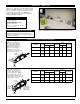
Data Cables egress out the back
(the side opposite the devices).
L L
T S
NOTE: Wiremold Open System, Ortronics Series II and TracJack modules
provided with all assemblies.
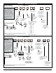
IMPORTANT
Use this chart to configure
your own custom
TableSource activation.
Many of the configurations
are standard offerings, and
can be quoted and delivered
to you quickly with the help
of our Wiremold Customs
group. Just call in with your
TableSource part number,
and they will be able to
supply you with a quote,
technical specifications and
a CAD Drawing.
Data Cables egress out
the back (the side
opposite the devices).
NOTE: Wiremold Open System, Ortronics Series II and TracJack modules
provided with all assemblies.
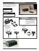
1. Select face for
mounting device.
Input letter.
7. Choose number of USB
modules. Input a number
followed by "U"
#U = Number of USB
Modules
3. Number of
duplexes
(from
1-4). Input
number.
5. Choose
number of
communication
adapters (from
1-4). Input
number.
6. Choose color of
activation and
devices. Input
two-letter
color code.
A Face
B Face
1U, 2U, etc.
Number of USB
Module #
followed
by "U"
LL
Color of Product
WH- Painted White with
black devices
BK- Painted Black with
Black devices
IV- Painted Ivory with
black devices
AL- Anodized Aluminum
with gray devices
L L
Face
of
Unit
A, B
L
Mounting
Syle
T, P
L
No. of
Duplexes
1-4
#
Whip
Exit
Y, Z
L
No. of
Comm.
Adapters
1-4
#
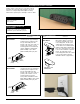
4. Choose face for 6'
[1.8m], three-wire
whip to exit.
2. Mounting styles
T – Mounting Ears
P – Mounting Stud
A Face
B Face
Y STYLE
Z STYLE
Product
Group
L L
T S
8. Choose if
Deadfront GFCI
Protection is needed.
If not, leave blank.
G = Dead Front
GFCI Module
G