WPS-565-DOM-A DOME CAMERA INSTALLATION MANUAL Review manual thoroughly before installation. Retain for future reference.
WPS-565-DOM-A Installation Manual Safety Instructions This information is provided to ensure your safety and to prevent physical or financial loss. Please read this document carefully before installing and operating the camera. 1. Handle with care. Use caution when handling to avoid damage to sensitive internal components. 2. Do not install camera under extreme temperatures. This camera only operates under temperature conditions between 14˚F ~ 140˚F. 3.
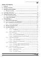
WPS-565-DOM-A Installation Manual Table of Contents 1. Features 5 2. Package Contents 6 3. Wiring Recommendations 7 3.1. Wiring Connections 7 4. Installation Instructions 8 5. Camera Operation Setup 10 5.1. Focus, Zoom and Position 10 5.2. Using the Test Adapter 10 6. OSD SETUP Menu 11 6.1. Default Settings Description 11 6.2. How to Navigate the OSD SETUP Menu 6.2.1. OSD Joystick (Test Adapter) 6.2.2. How to Save Settings 12 12 12 6.3. OSD Menu Structure Outline 13 6.4.
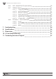
WPS-565-DOM-A Installation Manual 6.4.6. 6.4.7. 6.4.8. DPC (Dead Pixel Compensation) SPECIAL Menus 6.4.7.1. CAM TITLE Setting 6.4.7.2. MOTION Detection 6.4.7.3. PRIVACY Setting 6.4.7.4. PARK LINE Setting 6.4.7.5. IMAGE ADJ. Setting 6.4.7.6. COMM ADJ. — RS485 Setup Exit Menu — Save and Reset 6.4.8.1. SAVE 6.4.8.2. NOT SAVE 6.4.8.3. RESET 20 21 21 21 22 22 23 24 24 24 24 24 7. Troubleshooting 25 8. Specifications 26 9. Dimensions 27 10. 5-Year Limited Warranty 27 11.
WPS-565-DOM-A Installation Manual 1. Features 1/3” 960H Sony Super-HAD II CCD The Sony Super HAD II CCD is ideal for low lux illumination, resulting in a clear and crisp image. Varifocal Auto-Iris Lens This camera features a varifocal lens with a focal length of 2.8-12 mm. The autoiris function intuitively manages the amount of light passing through the lens for consistent image brightness.
WPS-565-DOM-A Installation Manual 2. Package Contents (1) WPS-565-DOM-A Camera (1) WPS-ACC-PWR-M AC/DC Power Plug (1) OSD Joystick / BNC Test Adapter (4) Surface Mounting Screws (includes 1 spare) (4) Wall Anchors (includes 1 spare) (1) 3mm Allen key (1) Foam gasket (1) Paper mounting template (1) Installation Manual (1) Spare Silica packet in vacuum sealed bag NOTE: A POWER SUPPLY IS NOT INCLUDED WITH THIS CAMERA. The PS-12DC-1A or WPS-PS multiple output power supplies are recommended.
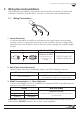
WPS-565-DOM-A Installation Manual 3. Wiring Recommendations Wiring should be installed, terminated, and tested for connectivity before the camera is installed. Specifications for each connection are detailed below. 3.1. Wiring Connections 1 12V DC Power In 2 BNC Video Out 3 RS485 Leads 1. Power (Required) It is recommended to install the camera power supply near the recording location and run a remote power wire to the camera. Use the voltage drop calculator at www.SnapAV.
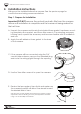
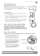
WPS-565-DOM-A Installation Manual 4. Installation Instructions Wiring must be installed before the camera. See the previous page for connections and wiring recommendations. Step 1. Prepare for Installation Important! DO NOT remove the protective plastic film from the camera dome until installation is complete and the camera is being sealed for the last time. A. Unpack the camera and locate the included foam gasket, hardware, mounting template, silica packet, and 3mm Allen wrench.
WPS-565-DOM-A Installation Manual Step 2. Mount the Camera Using Mounting Accessories Mount the accessory according to its instructions, make wiring connections, and mount the camera. Then, continue these instructions below at Step 3 to complete camera installation. Surface Mounting A. Use the included template to mark the screw locations for mounting. B. Connect the camera to the wiring and move it into position. Avoid pinching the wires between the camera and the mounting surface. C.
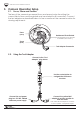
WPS-565-DOM-A Installation Manual 5. Camera Operation Setup 5.1. Focus, Zoom and Position The lens of the camera has manual focus and zooms knobs for setting the correct field of view and the gimbal may be rotated for tilt correction. Connect the test adapter as described below to use a monitor at the camera location for viewing adjustments. Focus (Front) Rotate and Pivot Gimbal (Loosen/tighten pivot setscrew Test Adapter as needed, not shown. ) Connection Zoom (Rear) Test Adapter Connector 5.2.
WPS-565-DOM-A Installation Manual 6. OSD SETUP Menu WPS-565 series cameras use an on-screen (OSD) menu system for setup of advanced image and control settings.
WPS-565-DOM-A Installation Manual 6.2. How to Navigate the OSD SETUP Menu The OSD menu is displayed as an overlay of the camera field-of-view. It will remain visible as long as the menu is active. Use the test adapter or RS485 to navigate. (use test adapter for initial setup. RS485 setup is detailed in section “6.4.7.6. COMM ADJ. — RS485 Setup” on page 24) 6.2.1.
WPS-565-DOM-A Installation Manual 6.3. LENS EXPOSURE OSD Menu Structure Outline DC MANUAL SHUTTER BRIGHTNESS AGC DWDR WHITE BAL. ATW AWB AWC->SET ANTI. CRL MANUAL BRIGHTNESS 0...42...255 IRIS SPEED 0...4...15 BRIGHTNESS 0...37...255 AUTO 1/60 FLK(1/120) 1/250 1/500 1/1000 1/2000 1/4000 1/5000 1/10000 1/100000 0...37...255 OFF LOW MIDDLE HIGH ON LEVEL 0...35...63 OFF COLOR TEMP AREA SEL. BLC MANUAL OUTDOOR INDOOR BLUE RED 0...19...255 0...24...
WPS-565-DOM-A Installation Manual CAM TITLE OFF OFF ON ON MOTION OFF PRIVACY ON OFF PARK LINE ON SPECIAL LENS SHAD. AREA SEL. AREA STATE HEIGHT WIDTH LEFT/RIGHT TOP/BOTTOM DEGREE VIEW 1~4 (all 4 are on by default) ON OFF 0...3...15 0...3...15 0...2...15 0...2...15 0...32...255 ON OFF AREA SELECT AREA STATE HEIGHT WIDTH LEFT/RIGHT TOP/BOTTOM COLOR 1~8 (all 8 are on by default) ON OFF 0...255 (default setting varies for each of the 8 areas) 0...
WPS-565-DOM-A Installation Manual 6.4. OSD MENU SETTINGS 6.4.1. LENS Menu The amount of light entering the camera lens is controlled by the size of the aperture, (called IRIS in SETUP menu). SETUP LENS DC • The default DC setting is recommended when lighting levels vary regularly. • For conditions with fixed, low-level lighting, the MANUAL setting may be ideal. Both settings offer additional setup options for fine tuning: • Set the lens mode on the main setup screen.
WPS-565-DOM-A Installation Manual 6.4.2. EXPOSURE Menu Exposure settings use the sensor in the camera to control how much light is recorded in each frame of video. EXPOSURE SHUTTER AGC DWDR RETURN AUTO MIDDLE OFF RET • Access the EXPOSURE sub-menu settings from the main SETUP menu. 6.4.2.1. SHUTTER Electronic shutter speed controls how much light gets to the camera sensor with each frame of video. • Use the default AUTO setting in normal lighting conditions.
WPS-565-DOM-A Installation Manual 6.4.3. WHITE BALANCE Menu White balance adjusts the image color according to the lighting conditions of the scene to correct for different lighting color ranges. SETUP WHITE BAL ATW • Move the joystick left or right to select the desired mode. 6.4.3.1. Auto Modes Auto modes are preset to match the color needed for several common types of light bulbs. Use the MANUAL setting below for other conditions. Move the joystick left or right to change the mode.
WPS-565-DOM-A Installation Manual 6.4.4. BACKLIGHT Menu Back Light Compensation (BLC, default) clarifies objects in front of bright light. For example, in a scene with lighting facing the camera, if a person walks toward a normal camera, they will appear as a silhouette, but BLC will adjust contrast for more detail. BLC is ideal where the field of view is focused close to the camera. High Light Compensation (HLC) blocks bright light from causing white-out.
WPS-565-DOM-A Installation Manual 6.4.5. DAY & NIGHT Menu The camera sensor has DAY (color) and NIGHT(black and white) mode. Use this menu to set up the mode, how it is switched and also IR levels. • Move the joystick left or right to select a mode and enter its sub-menu (if applicable). Not all menus are displayed due to similarities in settings. 6.4.5.1. D&N EXT (External Sensor) By default (D&N EXT), the color mode is set based on a light sensor on the front of the camera.
WPS-565-DOM-A Installation Manual 6.4.6. DPC (Dead Pixel Compensation) Dead Pixel Compensation automatically removes defective pixels and “fills in” the image. Use the UP arrow function to exit this menu without performing DPC. DPC DPC VIEW LS VALUE DIFF.
WPS-565-DOM-A Installation Manual 6.4.7. SPECIAL Menus 6.4.7.1. CAM TITLE Setting The CAM TITLE sub-menu provides the ability to set a camera name and have it appear on the screen. • CAM TITLE — Set to ON to display the camera name on the screen. • Set a camera name by selecting one letter/number at a time using the menu at the bottom of the screen. Assigning a name that highlights the location of the camera such as Lobby, Main Hall, etc. is recommended.
WPS-565-DOM-A Installation Manual 6.4.7.3. PRIVACY Setting Privacy Mask allows the masking of up to 8 “surveillance-free” zones in the field of view. This may be used for a camera that has a neighbor’s window in part of the scene, or with an area where sensitive information would be visible. PRIVACY AREA SEL.
WPS-565-DOM-A Installation Manual 6.4.7.5. IMAGE ADJ. Setting IMAGE ADJUST LENS SHAD. 2DDNR MIRROR FONTCOLOR CONTRAST SHARPNESS DISPLAY NEG. IMAGE RETURN OFF ON OFF | | 119 024 CRT OFF RET | | | | | | | | | || | | | | | | | | | | | | | | || | | | • LENS SHAD. — This feature brightens the corners of the image when using a wide angle view. Scroll left or right to toggle OFF or ON. • 2DNR — 2D-DNR digital noise reduction produces clear images in low light conditions.
WPS-565-DOM-A Installation Manual 6.4.7.6. COMM ADJ. — RS485 Setup Set up remote control of the camera’s OSD SETUP menu from a PTZ controller or DVR through RS485. COMM ADJ CAMERA ID BAUDRATE PROTOCOL DISPLAY ID ID POS RETURN 001 4800 PELCO-D OFF RET • CAM ID — Scroll left or right to select a unique ID number from 0 to 225 to identify the camera on the RS485 loop. Note: Each device in the RS485 connection MUST be set to a unique address number for proper RS-485 communication.
WPS-565-DOM-A Installation Manual 7. Troubleshooting If you have trouble operating the camera, first refer to the following guidelines. If the problem persists, contact Technical Support at (866) 838-5052. Nothing appears on the display: • Check if the power for the camera and the monitor is ON. •C heck if the VIDEO cable is connected to the camera BNC video output jack. • Check if the VIDEO cable is connected to the monitor VIDEO input jack.
WPS-565-DOM-A Installation Manual 8. Specifications Imaging Image Sensor 960H 1/3" Color Sony Super HAD II Lens 2.8 ~ 12mm Auto Iris Vari-Focal Lens Estimated Horizontal Viewing Angle Resolution (TVLs) Effective Pixels Gamma S/N Ratio Sync.
WPS-565-DOM-A Installation Manual 9. Dimensions 5.91" Maximum Camera Angle 4.04" Side View 67.0° 67.0° Top View 10. 5-Year Limited Warranty This camera has a 5-Year Limited Warranty. The warranty includes parts and labor repairs on all components found to be defective in material or workmanship under normal conditions of use. This warranty shall not apply to products which have been abused, modified, disassembled or improperly installed.
140422-1720 © 2014 Wirepath Surveillance