
User manual


Copyright © Dr Robot Inc. 2005
102
When using the DUR5200 with the third party controller, the power supply and the input/output
signals should be connected properly (please refer to Section VII.3 Connections). The basic operation
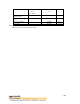
is illustrated in Figure VII.1.
Range measurement starts from the rising edge of TE. Then the controller set TE to low (logic 0) after
t1 (250 µsec). The controller should measure the time interval td from the rising edge of TE to the first
rising edge of RS, which is the returned sound wave. td is equal to two times of the traveling time
between the sensor to the object (transmitting and echoing). The time period between two
measurements should be no less than 20 msec. The minimum distance that the DUR5200 can
measure is 4 cm. This means that if the range is less than 4 cm, it will be reported as 4 cm.
Figure VII.1 Basic Operation Timing
The distance to object (in meter) can be obtained as follows:
Distance to object (in meter) = td (in second) * v (in meter/second) / 2
VII.3 Connections
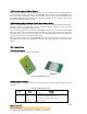
VII.3.1 Board Structure
Figure VII.1 illustrates the structure of the board.
Figure VII.1 DUR5200 Structure
VII.3.2 Connector Description
The DUR5200 can be connected to the controller system via a 4-pin 2.54 mm-pitch single row
connector:
Table VII.1 Ultrasonic Range Sensor Connectors
Pin Name Function
1 Vcc Positive power source, 5 V DC
2 RS Ultrasonic echo receiving signal, active rising edge output
3 TE Ultrasonic transmitting enable, active high input