
User manual


Copyright © Dr Robot Inc. 2005
105
+ Y
- Y
+ X- X
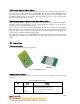
Figure VIII.2 Acceleration sensing directions
To measure the tilt or orientation of an object, the DTA5102 should be mounted in such a way that the
axes of sensitivity are parallel to the surface of the Earth. In this configuration, the relationship
between the output voltage and the tilt angle of each axis is shown by the following equation
V
OUT
= V
ZEROG
+ (
G
V
∆
∆
×
G
×
θ
sin )
Where
V
OUT
= Output voltage of each axis
V
ZEROG
= Voltage at zero g
GV ∆∆ = Sensitivity
G = Earth’s gravity (~9.81)
θ
= Tilting angle
GV ∆∆ can be obtained by experiment by placing the sensor level (so that the gravity vector is
perpendicular to the measured sensor axis) to take the V
ZEROG
reading. Then, you should rotate the
sensor so that the gravity vector is parallel with the measured axis and take the V
ONEG
reading. The
equation then can be rewritten as:
V
OUT
= V
ZEROG
+ [ (V
ONEG
- V
ZEROG
)
×
θ
sin ]
The tilting angle then can be calculated by ArcSin () function or by Taylor polynomial approximation
θ
= sin
-1
(z) =
+
z
40
3
6
53
zz
+ +... 1<z
To detect the high frequency data, the sampling rate must be at least twice of the signal frequency
according to Nyquist Sampling Criterion. As a rule of thumb, using 5 to 10 time higher sampling rate
will get good results for data recovering. Using some digital filter may require even higher sampling
rate. However, sampling rate higher than 20 KHz is generally not recommended for the DTA5102
module. Also, be aware of the signal aliasing effects.
The relationship between the output voltage and the acceleration in each axis direction is shown by
the following equation
V
OUT
= V
ZEROG
+ (
G
V
∆
∆
×
Acc)
Where
Acc = value of the acceleration.