
User manual


Copyright © Dr Robot Inc. 2005
106
VIII.2.2 Running as part of WiRobot System
When using the DTA5102 with the WiRobot system, user can simply connect the module to the tilt
sensor module connector on the PMS5005 controller board and the PMS5005 built-in sensor device
driver will take care of the data acquisition. Users can simply call a function offered by the WiRobot
SDK software on PC (requires Microsoft platform) or send a data request packet (platform
independent) to obtain the data.
VIII.2.3 Running as a General Purpose Tilt and Acceleration Sensor Module
When using the DTA5102 with the third party controller, the power supply and the input/output
signals should be connected properly (please refer to Section VIII.3). The controller can get the tilt
and acceleration data via an analog to digital converter. The value of the angle or the acceleration can
be calculated according to the equations in Section VIII.1.
For premium performance, several cautions need to be taken into account when operating the system:
• The power supply voltage should be 5 VDC nominal.
• The length of the cable connecting the DTA5102 and controller should be as short as possible.
• The DTA5102 module and the controller should not be in a high current path.
• If using switching power supply, be aware of the switching frequency may interfere with the
DTA5102 module.
VIII.3 Connections
VIII.3.1 Board Structure
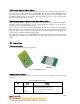
Figure VIII.3 shows the board structure.
Figure VIII.3 DTA5102 Structure
VIII.3.2 Connector Description
The DTA5102 can be connected to the controller system via a 4-pin 2.54 mm-pitch single row
connector:
Table VIII.1 Tilt and Acceleration Sensor Connectors
Pin Name Function
1 VCC Positive power source, 5 V DC
2 YOUT Y direction signal, analog output
3 XOUT X direction signal, analog output
4 GND Power supply ground