
User manual


Copyright © Dr Robot Inc. 2005
109
IX.2.2 Running as Part of WiRobot System
When using the DHM5150 with the WiRobot system, user can simply connect the module to one of
the human sensor module connectors on the PMS5005 controller board and the PMS5005 built-in
sensor device driver will take care of the data acquisition. Users can simply call a function offered by
the WiRobot SDK software on PC (requires Microsoft platform) or send a data request packet
(platform independent) to obtain the data.
IX.2.3 Running as a General Purpose Human Motion Sensor Module
When using the DHM5150 with a third party controller, the power supply and the input/output signals
should be connected properly (please refer to Section IX.3). The controller can get the human
information data via an analog to digital converter.
There are analog outputs, one is the human motion (MS), and the other one is the human alarm (AS).
When no human presents, output voltage of MS and AS is 1.5V. The change of AS is basically 5 times
larger than MS due to the on-board amplifier. The closer the human and the faster the motion will
cause the longer voltage change shown in MS and AS.
Note that when using two sets of the DHM5150 for human motion detection, the moving direction
information can be identified by analyzing the pattern, timing and magnitude of two sensor output
signals.
IX.3 Connections
IX.3.1 Board Structure
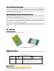
Figure IX.2 illustrates the structure of the board.
Figure IX.2 DHM5150 Structure
IX.3.2 Connector Description
The DHM5150 can be connected to the controller system via a 4-pin 2.54 mm-pitch single row
connector:
Table IX.1 DHM5150 Connector
Pin Name Function
1 Vcc Positive power source, 5 V DC
2 MS Human motion signal, analog output
3 AS Human presence alarm, analog output
4 GND Power ground