
User's Manual


Wisen Innovation Technical Doc. No.2019 WISENMESHNET® L-Series Omni Tilt & Distance Sensor Node - User Manual
www.wisencn.com Page - 8 - of 15
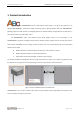
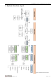
Figure 3. Omni Tilt & Distance Sensor Node Internal Configuration Terminologies, where:
No.
Terminology
1
Mesh Antenna
2
On/Off Switch
3
Laser Distance Sensor
4
Laser Pointer Switch, i.e., laser constantly on during installation
5
Mesh Program Port
6
ER 34615 3.6V D Cell Battery
5. Operation Procedures
5.1.System Deployment Notifications
1) Location: The deployment location of a Omni Tilt & Distance Sensor Node is usually determined by the desired
monitoring or inspection location;
2) Before any Omni Tilt & Distance Sensor Node is switched on, a gateway must be deployed, powered on and
proven to be working properly. Otherwise, the nodes will need to be switched off and on again after a gateway is
switched on. So simply speaking, the rules to follow when deploying and turning on a WISENMESHNET system
are:
Gateway first, then nearby nodes, then further nodes.
3) All the Omni Tilt & Distance Sensor Node should face to the same direction, and clear notes must be taken so
that the Laser Distance Sensor direction of a monitored structure can be correctly interpreted;
4) The Omni Tilt & Distance Sensor Nodes must be oriented with at least one axis marked on the label parallel to the
horizontal plane, so that the tilting angle data can be easily recognized and interpreted;
5) All the Serial Numbers of the Omni Tilt & Distance Sensor Nodes must be recorded against their site references;
6) All the node should have its antenna point upwards/downwards.