WT-9001 IP65 G GS SM MR Re em mo otte eM Mo on niitto orriin ng g A An nd d R ysstte em m Re em mo otte eC Co on nttrro oll S Sy User Manual & Setting Instructions W R R R W T U A C O P O A T O N S D N B H D WIIIT TU UR RA AC CO OR RP PO OR RA AT TIIIO ON NS SD DN NB BH HD D
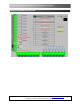
WT-9001 IP65 GSM Remote Monitoring & Remote Control System WIRING DIAGRAM DESCRIPTION WT-9001 IP65 – USER MANUAL – Rev. 4.7 – Technical Support: technical@witura.
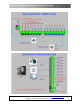
WT-9001 IP65 GSM Remote Monitoring & Remote Control System CONNECTION DETAILS WT-9001 IP65 – USER MANUAL – Rev. 4.7 – Technical Support: technical@witura.
WT-9001 IP65 GSM Remote Monitoring & Remote Control System WT-9001 IP65 – USER MANUAL – Rev. 4.7 – Technical Support: technical@witura.
WT-9001 IP65 GSM Remote Monitoring & Remote Control System PACKAGE CONTENTS 1) 2) 3) 4) 5) 6) 1 1 1 1 1 1 pc pc pc pc pc pc IP65 Enclosure WT-9001 Main Board with GSM Module mounted Power Adapter Battery Backup GSM Antenna LCD Display for Assisting in Programming CONTENTS 1. Introduction………………………………………………………………………………………………………………6 2. Features………………………………………………………………………………………………………………………6 3. Characteristic……………………………………………………………………………………………………………6 4.
WT-9001 IP65 GSM Remote Monitoring & Remote Control System 1. INTRODUCTION The WT9001 IP65 GSM Remote Monitoring & Remote Control System is a complete remote telemetry unit. It contains a GSM Modem and control circuitry. It is capable of controlling up to 8 Relay outputs and monitor 8 Digital inputs and 4 Analogue inputs. (Analogue input support: Detect Water Leaks, Monitor Temperatures for out-of-range conditions, Monitor Humidity for Damaging High Humidity Levels and monitor fuel levels).
WT-9001 IP65 GSM Remote Monitoring & Remote Control System 3.1 Standalone Operation Housed in the weather and desk proof IP 65 enclosure complete with internal industrial modem, monitoring controller and flexible operating firmware. It is very easy to setup, install and use. 3.2 8 Digital Inputs Most equipment today does provide some form of alerting signal to interface to monitoring devices from reporting of various malfunction or abnormalities.
WT-9001 IP65 GSM Remote Monitoring & Remote Control System 3.4 8 Digital Outputs WT-9001 is a 2 way device. Besides monitoring inputs and act upon such inputs it also allow mobile phone users to compose SMS messages to it. When WT-9001 receives any SMS, it will look its memory bank to see what it is supposed to do and action according. No action SMS are ignored. Up to 8 relays can turned on and off by messages received from mobile phone.
WT-9001 IP65 GSM Remote Monitoring & Remote Control System 3.9 GSM Modem Integral to the design of WT-9001 is a GSM 850/900/1800/1900mhz Industrial grade modem. Its capabilities and performance are highly optimized by the operating firmware. Any change in the GSM signal and receiving conditions are detected quickly and the software automatically takes care of signal errors 3.
WT-9001 IP65 GSM Remote Monitoring & Remote Control System 4. INSTALLATION INSTRUCTION Note: It is essential that you read the step by step instructions fully prior to installing and programming the unit 4.1 Screw off the Front Case of WT-9001 IP65 Main Unit 4.2 Installing the Components: Antenna, LCD, Power Supply & SIM Card Installing the SIM Card Note: Installing the SIM Card. Please be sure the initial 4 digit PIN code of SIM card is disabled.
WT-9001 IP65 GSM Remote Monitoring & Remote Control System 4. Slide the SIM door to lock the SIM card in place You should install the WT-9001 in a place where there is GSM signal coming from the operator you want to use. Check it with a phone before proceeding with the installation. If you need to install the device in a place with little signal, you may consider using an external antenna that we may supply as an option to be purchased separately with 5m cable. 5.
WT-9001 IP65 GSM Remote Monitoring & Remote Control System Note: Programming the administrator numbers is necessary in order to operate all other functions and to receive text alerts when the relays activated. 5.2 Access Control For Administrator Note: It is advised that the owner should set the system to allow programming access for administrators only after programming the Administrator numbers.
WT-9001 IP65 GSM Remote Monitoring & Remote Control System Example of Returned Message: *RLY5=3600 OK Note: Sending the following SMS Message to unit will switch off the relay *RLY5#0 To check the status of a single relay, you would send the following example text message (check status of relay 1) to the unit. *RLY?1# To check the status of all the relays, you would send the following text message to the unit. *RLY?# 5.3.
WT-9001 IP65 GSM Remote Monitoring & Remote Control System Text Command: *RETR#XXXXXXXXXXXXXXXXXXXX X stands for position for 1 - 20 administrators with function value: 0 (OFF), 1 – 9 (number of SMS alerts) Example: To program the unit to generate 2 SMS to administrators 1, 2, 3, 4, 5 and 1 SMS to the rest, you would send the following SMS message to the unit.
WT-9001 IP65 GSM Remote Monitoring & Remote Control System To disable input 1, you would send the following SMS to the unit. *CTR1#0 Returned Message: #INCTR1=OFF OK Note: A disabled input will not trigger an alarm or report 5.4.2 Setup the Working Mode of 4 Analogue Inputs Input 1, 2, 3 and 4 of WT-9001 can be configured to an analogue inputs signal.
WT-9001 IP65 GSM Remote Monitoring & Remote Control System 5.4.3 Setting the Alarm Set Points for Analogue Input Note: This Function Works On Analogue Input Only There are 4 alarm set points available on each analogue input. It allows the unit to generate alarms whenever the monitored signal reaches the set point. To program the alarm set points, you can send the following command by SMS to the unit.
WT-9001 IP65 GSM Remote Monitoring & Remote Control System Function 8: Turn off output relay 6. The unit will send SMS if the relay 6 is ON at previous state. If not it won’t send SMS. Function 9: Turn off output relay 7. The unit will send SMS if the relay 7 is ON at previous state. If not it won’t send SMS. Function 10: Turn off output relay 8. The unit will send SMS if the relay 8 is ON at previous state. If not it won’t send SMS.
WT-9001 IP65 GSM Remote Monitoring & Remote Control System 5.4.5 Reset the Alarm Set Points This function allows you to reset an input’s alarm set points to factory default settings. To reset alarm set points, you can send the following command by SMS message to the unit. Text Command: *CLP[N]# N stands for Input number 1 - 4 Example: To reset input 1 alarm set points to factory default, you would send the following SMS message to the unit.
WT-9001 IP65 GSM Remote Monitoring & Remote Control System N stands for input number 1 – 12 (1 – 4 for Analogue and 5 – 12 for Digital) X stands for position for 1 - 20 administrators with function value: 0 (OFF), 1 – 9 (number of text alerts) Example 1: Any alarm coming from Input 1 will generate 2 SMS to administrators 1, 2, 3 and 1 SMS to the rest, you would send the following SMS message to the unit.
WT-9001 IP65 GSM Remote Monitoring & Remote Control System Example: If you want the alert message to display “Garage Opened!” when input 1 triggered; you would send the following SMS message to the unit. *STR1#Garage Opened! To check the programmed texts, you can send *STR?#[N] 5.4.9 Editing the Input Alert Message For (When Input returned to Normal) The Input Alert Message can be edited and programmed up to 50 characters long.
WT-9001 IP65 GSM Remote Monitoring & Remote Control System Example: Assume that you want it to send a counter alert message each time the input 5 has triggered for 5 times, you would send the following SMS message to the unit. *COA5#5 5.4.11 Setting the Feature Of Digital Input All digital inputs can be programmed to behave differently, it can count the input active high pulses, generate an alarm message or activate relay.
WT-9001 IP65 GSM Remote Monitoring & Remote Control System Function 4: Function as pulse counter Activate the output relay number (according to the input number applied) for 2 second and off. Eg. If pulse counter 4 at Digital Input 8 reached the alert value, relay 4 will activate.
WT-9001 IP65 GSM Remote Monitoring & Remote Control System Audible alarm will sound when input return to normal (if the alarm function is turned on (*ALM[N]#1)) Function 9: Function as pulse counter Switch off output relay 1 Function 10: Function as pulse counter Switch off output relay 2 Function 11: Function as pulse counter Switch off output relay 3 Function 12: Function as pulse counter Switch off output relay 4 Note: It is required to reset the Counter Alert Value (
WT-9001 IP65 GSM Remote Monitoring & Remote Control System 5.4.13 Setting the Function of Opening & Closing time for Output Relay The system has the function to activate the relay for a specific time and then be deactivated for a specific time in a repeating process. To set the opening & closing time of the relays, you can send the following SMS command to the unit. Note: This function only applied in input function 5 and 6.
WT-9001 IP65 GSM Remote Monitoring & Remote Control System N stands for Input number 1 – 12 X stands for ON (1) or OFF (0) value When *ALM1#1 is applied, means audible alarm will sound when Input 1 triggered. When *ALM1#0 (Default) is applied, means audible alarm will not sound when Input 1 triggered. To check the audible siren function setting, you can send *ALM?#[N] 5.5.
WT-9001 IP65 GSM Remote Monitoring & Remote Control System Power down and text alert received: Power down Power restored and text alert received: Power restored 5.5.4 Setting the Recipient of AC Failure Alert Whenever there is power failure, the unit can generate text alerts to all 20 of the administrator’s Mobile phone numbers. To set the administrator to receive this alert, you would send the following commands by SMS message to the unit.
WT-9001 IP65 GSM Remote Monitoring & Remote Control System Alert message received: WARNING! SIM Card Has Been Changed On WT-9001 To check the Anti-Theft setting, you can send *ANTH?# 5.5.6 Setting the Recipient of Anti-Theft Alert With Anti-Theft function turned on, it can generate text alerts to all 20 of the administrator’s Mobile phone numbers whenever the SIM card has changed. To set the administrator to receive this alert, you would send the following commands by SMS message to the unit.
WT-9001 IP65 GSM Remote Monitoring & Remote Control System Text Command: *USID#XXXX XXXX stands for 4 digits numeric numbers Example: To program User ID 1111 into the WT-9001 device, you would send the following SMS command to the unit. *USID#1111 Note: To setup a User ID for the monitoring software, please refer to the WT-9001 Server Software Guide. To check the programmed User ID, you can send *USID?# 5.6.
WT-9001 IP65 GSM Remote Monitoring & Remote Control System 5.6.3 Setup the GPRS Communication To link the WT-9001 unit to the monitoring software, you will need to program the connection type, external IP address of the host computer and Port number created from the monitoring software into the WT-9001 unit by sending the following SMS command. Text Command: *GSIP#TTT,XXX.XXX.XXX.XXX,NNNN TTT stands connection type “TCP” XXX.XXX.XXX.
WT-9001 IP65 GSM Remote Monitoring & Remote Control System 5.7 MISCELLANEOUS SETTINGS 5.7.1 Inquire All Programmed Administrator Numbers To check all the administrator number in the list, simply send the following SMS command. Text Command: *ADM?# 5.7.2 Inquire the Status of Inputs To check input status, you can send the following SMS command.
WT-9001 IP65 GSM Remote Monitoring & Remote Control System 5.7.4 Reading the Alarm Time Value It is possible to read the alarm time value by sending the following SMS command to the unit. Send the following SMS Command: *ALT?# Example of Returned Message: ALT=30 OK Note: All 8 Digital Inputs have the same setting for siren on time (Default: 30 sec) 5.7.5 Reading the Total Increment Counter Value To read the total increment counter value, you can send the following SMS message to the unit.
WT-9001 IP65 GSM Remote Monitoring & Remote Control System 5.7.7 Reset the Total Increment Counter Value To reset the total counter value, you can send the following SMS message to the unit. Text Command: *CLA[N]# N stands for Input number 5 – 8 Example: When *CLA5# is applied, means the total increment counter value will be reset for input 5 5.7.
WT-9001 IP65 GSM Remote Monitoring & Remote Control System Text Command: *TEST# When the unit replies TEST-OK indicate the unit is operating correctly. Note: If you receive no reply then unit is not working 5.7.11 Setting the Password for Reset Command To setup a password for reset command, you can send the following SMS command to the unit.
WT-9001 IP65 GSM Remote Monitoring & Remote Control System 5.7.14 Checking the Back-up Battery Status To check the battery voltage and charger status, you can send the following SMS command to the unit. Text Command: *CHARGER?# 5.7.15 Checking the Software and Hardware Version of WT-9001 To check the software and hardware version of WT-9001, you would send the following SMS command to the unit. Text Command: *EDI?# Example of Returned Message: Software release time:2009/6/02/01:40HW:1.8SW1.0MW3.
WT-9001 IP65 GSM Remote Monitoring & Remote Control System 5.7.17 Auto Restart System The WT-9001 can continuously monitor the system status of its own. When there is a problem with system operation or the module is not working properly, it will restart the system automatically to avoid the unit stopped working permanently. If the system failed to respond within 15 – 30 seconds, it will restart the system. 6.
WT-9001 IP65 GSM Remote Monitoring & Remote Control System WARRANTY Witura Corporation Sdn Bhd guarantees all WT-9001 IP65 GSM Remote Monitoring And Remote Control System against defective parts and workmanship for 1-year warranty. Witura Corporation Sdn Bhd shall, at its option, repair or replace the defective equipment upon the return of such equipment to any Witura branch.