
Owner's manual

2
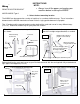
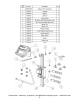
2- Permanently attached the scale and sensor to the lift
Center punch the screw locations and use the 3.6mm drill bit and the M4 x 8mm long thread forming
screws to attach the scale to the top plate (FIG 5) and the magnet bracket to the carriage (FIG 6). Put a
drop of oil on the end of the screws and use a nut driver to force the screws into the holes while turning
slowly.
Using a square make sure the scale is perpendicular to the top plate. If needed you may have to carefully
bend the “L” bracket to get perfect alignment. Fully tighten all screws to hold the system in position.
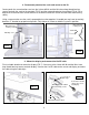
3- Mount the display and connect the Cat 5E cable
Find a suitable location to mount the display (FIG 7). You can use the 3.6mm drill bit and the M4 x 8mm
long thread forming screws to attach display. Connect the Cat 5E cable to the sensor and display and route
the cable using the cable clips.
M4 x 8 thread
forming screw
3.6mm drill
FIG 6
Add drop of oil
M4 x 8 thread
forming screw
3.6mm drill
Add drop of oil
FIG 5
FIG 7
Position the display mounting bracket
FIG 8
Alternate bracket position
Connect the Cat 5E
cable to the sensor
and display
Loosen nuts to
adjust angle
Attach using M4 X 8mm
thread forming screws