
User's Manual
MPR series User’s Manual: Draft version 0.95 11/4/04 page 22
be simultaneously present in the field of the reader and read ‘simultaneously’ from the viewpoint
of the user. RFID techniques permit automated information handling to a much greater extent
than bar codes.
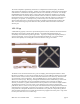
• ROBUSTNESS: Bar codes cannot be read if the printed code becomes dirty, defaced, or
excessively bent or curled. RFID tags are robust to dirt, paint, ink, and to some extent mechanical
damage, and can be read (albeit with reduced range) when misoriented or mechanically distorted.
RFID tags are tougher than bar codes.
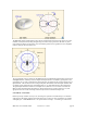
1.5.3 RFID system components
An RFID system is composed of (at least) a reader, one or more antennas, and one or more compatible
tags. In many applications it may be necessary or helpful to create human-readable labels incorporating
RFID tags; in this case an RFID tag printer is also very useful. While standalone RFID systems are
appropriate in some circumstances, more commonly the RFID reader is just a sensor that needs to interact
with a larger information system in order to be useful. Middleware is used to enable the interaction
between the reader and the network, and to filter and aggregate the large amounts of data the reader collects
into a more useful compendium provided to the network.
1.5.3.1 Reader
A UHF RFID reader is a radio transmitter and receiver. Most readers are capable of interrogating passive
tags, and are equipped with certain features uniquely suited to use for communicating with passive RFID
tags. A reader reading passive tags simultaneously communicates with the tag population and provides
power to operate the integrated circuits contained in the tags. During transmission, the reader transmits an
amplitude-modulated signal that is received by tags within range. The transmit power is generally limited
by regulatory requirements; for example, in the United States, no more than 1 watt average RF power may
be transmitted. Modulation rate varies depending on the standard employed, but is typically a few tens of
kilobits per second for UHF tags. Special coding of the transmitted data is employed to maximize the
power available to the tags.
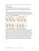
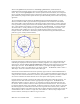
Once the tags have been powered up and received their instructions from the reader, they take turns
responding with their UID. Because of the unique requirements of the backscatter radio system used by
passive and semi-passive tags, the reader must continue to transmit a non-modulated (continuous-wave or
CW) signal while it listens for tag responses. The tags employ the CW signal to continue to provide power
to the tag electronics, and modulate the impedance of their own antennas in order to vary the signal
reflected back to the reader. The reader must extract the very small tag reflections from all the other
reflected signals it encounters. The MPR-series cards use one antenna for both transmit and receive
functions. [ MPR6000 and MPR7000 readers have two external antenna connectors. However, only one
antenna is in use at any given time, for both transmit and receive. The reader can switch from one antenna
to the other in order to cover differing physical regions, such as the high and low portions of a doorway, or
to avoid missing tags because of local losses of signal strength – fading – that are sensitive to the exact
position of the antenna and other objects.] Even with a well-matched antenna, the reflection from the
antenna back to the reader is much larger than any other reflected signal, and represents the main obstacle
to receiving the tag reflection. Degraded antenna match will lead to an increased antenna reflection,
making it harder for the reader to extract the tag signal and thus reducing read range. The antenna match is
sensitive to the immediate antenna environment (objects within a few cm of the antenna). For best results,
antennas should always be mounted in accordance with manufacturer’s recommendations, and free of
obstructions for at least 50 cm (20 inches) in the read direction.
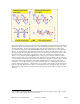
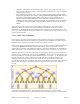
In the United States, readers are required by law to hop randomly from one frequency channel to another
when operating within the ISM band, residing for no longer than 0.4 seconds at any one frequency. In
addition, regulations forbid coordination of hopping patterns between collocated transmitters. When
configured for US operation, the MPR series uses 50 channels separated from one another by 500 KHz, and