
User's Manual

MPR series User’s Manual: Draft version 0.95 11/4/04 page 26
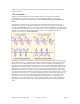
antenna is the patch antenna (also known as a microstrip or panel antenna). Patch antennas are
manufactured using techniques similar to those used to make printed circuits, and are inexpensive and
robust. They use a metal ground plane above which are printed resonant metal blocks; as a consequence
they are generally flat and radiate primarily in the direction opposite the ground plane. Most commercial
patch antennas are packaged inside a plastic radome to provide mechanical protection and a more pleasing
appearance.
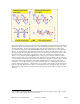
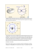
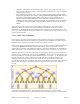
The recommended directional antenna for the MPR6000/7000, the Maxrad MP9026CPR, is a patch
antenna, with about 8.5 dBiC of gain in the direction perpendicular to the rounded face of the radome.
(The notation ‘dBiC’ indicates that the gain is that which would be measured using a circularly polarized
receiving antenna; a linearly polarized received would find 3 dB less power in the direction of maximum
gain.) Patch antennas can be linearly or circularly polarized. The MP9026CPR is circularly polarized.
As discussed above, circular polarization is a good choice when the tag orientation is not known. The
patch antenna, being of higher gain, will provide a significant improvement in read range over the
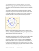
monopole antenna. Shown below is the radiation pattern of this antenna along the azimuth (horizontal
plane for a typical vertically-mounted antenna).
In principle, antenna gain could be increased to increase read range. However, in most jurisdictions, the
maximum gain employed in unlicensed operation is limited by regulation. For example, in the United
States, the FCC limits the effective isotropic radiated power (EIRP, the product of the actual power and the
antenna gain) to 4 watts. For the MPR6000, which is rated at _ watt output, the highest antenna gain
legally allowed is a factor of 8 (9 dB) relative to an isotropic antenna. The MPR7000, which is rated at 1
Watt output, cannot use an antenna with more than 6 dBi of gain.
Note that the recommended antennas have been specifically approved for use with the MPR6000/7000 in
the United States by the FCC. FCC regulations (title 47 part 15) require that antennas be approved for use
with specific radio communications devices, unless they are installed by a professional installer, and that in
all cases the combination of antenna and radio device must operate within regulatory constraints.
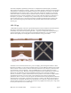
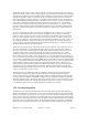
External antennas are generally connected to the reader using flexible coaxial cables and connectors. It is
important to select these cables and connectors appropriately for the application. The MPR6000 and
MPR7000 use MMCX connectors, which are very small and convenient for the limited form factor of a
PC-card slot. However, MMCX connectors must be protected from mechanical stress. This can be done
by using fine-diameter cabling, such as RG-405, to make the connections to the card. However, such cable
has relatively high losses, and should not be used for runs longer than about 2 meters (6 feet). When the
antenna must be mounted a long distance from the cable, an adaptor should be used at the end of a short run
of small-diameter cable to connect to a larger cable, such as RG-213 or RG214, using an adaptor to the
relevant connector, which may be an SMA or N-type connector.