RMT-170e HD Series • RMT-170e-HD • RMT-170e-SD 17-Inch High Definition Video Monitors User Guide Part Number 821042, Revision A
© 2011 Wohler Technologies, Inc.. All rights reserved. This publication is protected by federal copyright law. No part of this publication may be copied or distributed, stored in a retrieval system, or translated into any human or computer language in any form or by any means electronic, mechanical, manual, magnetic, or otherwise, or disclosed to third parties without the express written permission of Wohler Technologies. Reproduction Licensed users and authorized distributors of Wohler Technologies, Inc.
RMT-170e HD Series User Guide Introduction Overview The RMT-170e HD Series monitors are an ideal solution for viewing many different types of HD/SD (up to 1080i and 720p) or analog video and computer input. These monitors come with many in-monitor display features including IMD, tally, time-code, closed captioning, format display, and area/title safe.
RMT-170e HD Series User Guide S a f e t y I n s tr u c ti o n s Safety Instructions IMPORTANT: 1. Read, keep, and follow all of these instructions; heed all warnings. 2. Do not use this equipment near water. 3. Use only a dry cloth to clean the equipment. 4. Do not block any ventilation openings. Install only in accordance with the instructions in the section entitled, “Unpacking and Installation” on page 3. 5.
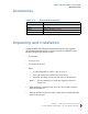
RMT-170e HD Series User Guide A c c e s s o r ie s Accessories Table 1–1 Optional Accessories Part Number 790017 790018 790019 790020 Description Table Top Stand Rack Ears Battery Mount (V Type) Battery Mount (Anton Bauer) Unpacking and Installation Unpack the RMT-170e HD Series monitor and inspect for any apparent physical damage that may have occurred in transit.
RMT-170e HD Series User Guide FCC Compliance 3. Use the included screws to attach either option. The table stand attaches on the rear bottom of the unit and the rack ears attach to the sides. 4. Use the included M3 x 12 mm screws to attach the optional battery mount, attach it to the rear of the monitor. 5. Place the RMT-170e HD Series monitor in the required location for operation. 6. Connect the required signals. For BNC connections use 75 -rated connectors. 7. Connect A.C.
RMT-170e HD Series User Guide Features de-interlacer. Analog signals are internally digitized with a high quality 10-bit over sampled analog to digital converter. Video inputs are provided for serial digital interface (SDI, 2 inputs) and DVI-I digital sources plus VGA (using DVI connector), component (YPrPb), Y/C, and CVBS analog signals. In addition to sixteen channels of SDI embedded audio, four channels of unbalanced analog audio are accepted with unbalanced outputs available for two channels.
RMT-170e HD Series User Guide S p e c if i c a ti o n s Specifications Physical Specifications Table 1–2 lists the specifications for the RMT-170e HD Series monitors. Table 1–2 Monitor Specifications Specifications RMT-170e-SD RMT-170e-HD Power 60 W; 1.5 A; 110 to 240 V AC (50 to 60 Hz) 16.32” W x 12.25” H x 2.83” D Dimensions (Without Stand) (414.5 mm x 311.2 mm x 71.8 mm) Rack Height 7RU Weight 17 lbs. (7.
RMT-170e HD Series User Guide S p e ci f i c a t i o n s Table 1–2 Monitor Specifications (Continued) Specifications Viewing Angles Operating Temperature RMT-170e-SD RMT-170e-HD 178° H x 178° V 32° F to 122° F (0° C to 50° C) Figures 1–3 through below illustrate the dimensions of the unit’s features in four different views. 8 2 1 0 4 2 : R M T- 1 7 0 e S e r i e s U s e r G u i d e © 2 0 1 1 Woh l er Te c h n o l o g i es , I n c . A ll r i g h t s r e se r ve d .
RMT-170e HD Series User Guide S p e c if i c a ti o n s Input/Output Specifications Table 1–3 Signal Type Overscan Input Output NTSC 684x462 PAL 684x548 SECAM 684x548 NTCS-4.
RMT-170e HD Series User Guide S p e ci f i c a t i o n s Table 1–4 below lists the signal formats that can be displayed on the RMT-170e-HD. Table 1–4 Format NTSC PAL SECAM NTCS-4.
RMT-170e HD Series User Guide S p e c if i c a ti o n s Table 1–5 Button/Signal-Terminal Relationships Input Signal Function Video/ Y/C YPbPr SD YPbPr HD SD SDI HD SDI HDMI DVI-D VGA Contrast Yes Yes Yes Yes Yes Yes Yes Yes Bright Yes Yes Yes Yes Yes Yes Yes Yes Chroma Yes Yes Yes Yes Yes Yes — Phase NTSC — — — — — — — NTSC Setup NTSC — — — — — — — Compo Level SMPTE 480I60a SMPTE SMPTE SMPTE SMPTE — — Color Temp.
RMT-170e HD Series User Guide S p e ci f i c a t i o n s Table 1–7 Analog Video Input Specifications Parameter Impedance Input Level Maximum Input Level Table 1–8 Impedance Return Loss Equalization SDI Video Output Specifications Parameter Signal Standard Impedance Return Loss Signal Level Overshoot Jitter Rise and Fall Time Note: Value SMPTE292M, SMPTE259M, ITU-R BT656; 270Mbps (525/625 SD component) 1485 Mbps (HD) 75 >18dB 5 MHz to 540 MHz Automatic equalizing to 30dB @ 270 Mb/s Signal Stand
RMT-170e HD Series User Guide Front Panel Controls Front Panel Controls The RMT-170e-HD monitor provides a variety of in monitor data including signal type, waveform/vectorscope, IMD (In-Monitor Display), audio meters, and time code. It also includes a three-color tally light above the display. Figure 1–1 illustrates the front panel features, and Figure 1–2 illustrates the front panel controls.
RMT-170e HD Series User Guide Front Panel Controls • Audio Levels: Levels for audio channels the are displayed on up to eight meters in pairs, as two or four meters on each side. The A model displays two to four meters. • IMD: The OSD Menu provides settings to customize the IMD (In-Monitor Display) text area to show a line of characters, numbers, and/or some symbols. The IMD displays in a 4:3 image and below a 16:9 image. • Speakers: Audio may selected for monitoring through the left and right speakers.
RMT-170e HD Series User Guide Front Panel Controls • SDI Input 1/2 (Button/Indicator): This indicator glows green when this input is selected for display on the monitor. As a control, this button selects the SDI signal for display to the monitor. • Line 1/2 (Button/Indicator): This indicator glows green when this input is selected for display on the monitor. As a control, this button selects the signal for display to the monitor.
RMT-170e HD Series User Guide Front Panel Controls Rotary Knob/Indicators The rotary knobs on the right side of the monitor’s control panel have multiple functions most of which are very similar and are listed immediately below: 1. Pushing the knob: Displays the current setting. Note: Pushing the Volume knob has a different function. See below. 2. Rotating the knob: Increases or decreases the value. 3. Indicator glows amber: If you select a value other than the default.
RMT-170e HD Series User Guide R e a r P a n e l C o n n e ct o r s Rear Panel Connectors Figure 1–3 on page 16 illustrates the rear panel connectors. Figure 1–3 RMT-170e-HD Rear Panel Tally Light GPI HD/SD-SDI I/O Configuration DVI RS-485 Analog Audio I/O Power Switch DC Power AC Power • Tally Light Control (GPI - RJ45): This connect provides control to the front panel (tri-color) tally light and other remote functions.
RMT-170e HD Series User Guide Rear Panel Connectors Table 1–10 GPI/Tally Lamp Color/Pin Designations Tally Lamp Color Green Red Orange GPI 1 Pin GND Open GND Table 1–11 Open GND GND GPI/Tally Lamp Connector Pin Out Pin 1. 2. 3. 4. 5. 6. 7. 8. GPI 2 Pin Function GPI 1 GPI 2 GPI 3 GPI 4 GPI 5 GPI 6 No Connection (NC) Ground • SDI Inputs 1 and 2: SD-SDI input signal on BNC jacks. • SDI Output: Output jack for selected SDI signal.
RMT-170e HD Series User Guide R e a r P a n e l C o n n e ct o r s • DVI-I (DVI-D/VGA/HDMI): Input jack for DVI analog/digital and requires an adapter for VGA or HDMI input signal. Note: The DVI-I signal type must be set in the USER CONFIG menu of the OSD Menu to function correctly. • RS485 I/O (RJ45): Connector for external control.
RMT-170e HD Series User Guide Using the OSD Menu Using the OSD Menu A description of how to use the OSD Menu follows. Also refer to Table 1–13 below for typical values and domain range. 1. Press the Menu button to display the menu. Note: 2. If you do not press another button for approximately 10 seconds, the menu will disappear from the screen. Use the Up and Down buttons to navigate through the seven sub-menu icons. The sub-menus are: A. STATUS B. COLOR TEMP C. MARKER D. VIDEO CONFIG E.
RMT-170e HD Series User Guide U s in g t h e O SD M e n u Table 1–13 Menu OSD Menu Structure Default Value Parameters Domain Range FORMAT COLOR TEMP COMPO LEVEL STATUS NTSC SETUP SCAN MODE Display only; Non-selectable. The values vary depending on input signal type and configuration settings.
RMT-170e HD Series User Guide Using the OSD Menu Table 1–13 Menu OSD Menu Structure (Continued) Default Value Parameters MARKER ENABLE ON Domain Range ON (enabled) or OFF (disabled) Selects the area marker aspect ratio according to the display aspect: • Aspect = 16:9 AREA MARKER 15:9 • Off • 4:3 Vertical • 15:9 Vertical • 14:9 Vertical • 13:9 Vertical • 1.85:1 Horizontal • 2.
RMT-170e HD Series User Guide U s in g t h e O SD M e n u Table 1–13 Menu OSD Menu Structure (Continued) Default Value Parameters Domain Range Sets the area marker mat transparency, where: MARKER (Continued) MARKER MAT OFF • OFF = Normal background, use line for area marker edge only • HALF = 50% Back ground brightness • BLACK = Black VIDEO CONFIG APERTURE 20 0 to 100 Used to select the audio source type, where: AUDIO CONFIG SOURCE TYPE EXT • EXT = Analog audio (Sets SPEAKER L and SPEAKER
RMT-170e HD Series User Guide Using the OSD Menu Table 1–13 Menu OSD Menu Structure (Continued) Parameters SPEAKER L Default Value AUD 1L (EBD 1) Domain Range Selects the audio channel assigned to the specified speaker based on the audio source type, where: • If SOURCE TYPE = NONE, then OFF • If SOURCE TYPE = AUD...
RMT-170e HD Series User Guide U s in g t h e O SD M e n u Table 1–13 Menu OSD Menu Structure (Continued) Default Value Parameters METER 1 OFF METER 2 METER 3 METER 4 Domain Range Selects the audio channel assigned to the left speaker based on the audio source type, where: • METER 5 METER 6 If SOURCE TYPE = NONE, then OFF • If SOURCE TYPE = AUD...
RMT-170e HD Series User Guide Using the OSD Menu Table 1–13 Menu OSD Menu Structure (Continued) Default Value Parameters Domain Range Sets the power saving mode (includes backlight and panel power supply, and signal to panel), where: AUTO STANDBY ON • ON = The monitor goes into power saving mode if no signal is input for about one minute. • OFF = The monitor keeps power on regardless of the input signal status.
RMT-170e HD Series User Guide U s in g t h e O SD M e n u Table 1–13 Menu OSD Menu Structure (Continued) Parameters UMD CHARACTER Default Value Domain Range RMT-170E-HD A user-definable input of up to 16 alphanumeric characters (also includes some symbols) Displays the time code, where: TC DISPLAY OFF • ON • OFF Displays the waveform: WAVE FORM OFF • VECT100 • VECT75 • WAVE • OFF Determines the location on the monitor where the waveform displays: • BOT LEFT = The waveform will cover t
RMT-170e HD Series User Guide Using the OSD Menu Table 1–13 OSD Menu Structure (Continued) Menu Parameters Default Value Domain Range Only available for NTSC (Y/C) signal types: CC OFF • OFF • CC1 through CC4 • TEXT1 through TEXT 4 • F1 BUTTON USER CONFIG MARKER F2 BUTTON AUDIO METER F3 BUTTON H/V DELAY XDS Sets the function for the designated button, where: • MARKER = Turns all markers ON or OFF • AUDIO METER = Turns all audio meter displays ON or (Continued) F4 BUTTON NATIVE F5 BUTTON
RMT-170e HD Series User Guide Using the Function (F) Keys Table 1–13 Menu USER CONFIG (Continued) CONTROL a b c OSD Menu Structure (Continued) Default Value Parameters GPI1 TALLY R GPI2 TALLY G GPI3 SDI 1 GPI4 SDI 2 GPI5 LINE 1 GPI6 LINE 2 KEY INHIBIT OFF Domain Range TALLY R, TALLY G, SDI1, SDI2, LINE1, LINE2, DVI-I, H/V DELAY, MONO, BLUE ONLY, NORMAL SCAN, OVER SCAN, NATIVE, ASPECT 4:3, ASPECT 16:9, or MARKER ENABLE Inhibits the use of all buttons except Power, Menu, and Volume: ON o
RMT-170e HD Series User Guide T e c h n i c a l F u n c t i o n a l O v e r vi e w Figure 1–7 RMT-170e-SD RS-485 Out (UMD, OSD Tally) RS-485 In L Audio Out Audio In 1 Audio In 2 SD-SDI Input 1 R Audio Source Select 2 LED Tally GPI Interface Programming RS-232 Interface 2 2 SDI Input Select 8 LCD 17” (16:9) with OSD SD-SDI SD-SDI Input 2 SD-SDI Select Out Re-clocked Line 1 Composite Video Composite A/D Video Decoder Video Source Select Audio Channel Select Line 2 Video/Y 4 to 8 for D
RMT-170e HD Series User Guide Technical Functional Overview Figure 1–8 RMT-170e-HD RS-485 Out (UMD, OSD Tally) RS-485 In L R Audio Out LED Tally Audio Source Select 2 Programming 2 Audio In 1 HD/SD-SDI Input 1 SDI Input Select 4 LCD 17” (16:9) with OSD SD-SDI HD/SD-SDI Input 2 HD/SD-SDI Select Out Line 1 Composite Video Composite A/D Video Decoder Video Source Select Audio Channel Select Line 2 Video/Y Line 2 Video/Pr 4-8 for De-embedded, 2-4 for Analog Composite or Component A/D Vide