
User manual


ALM26 Series User Manual P/N 821644 Rev-A
5
© 2006 Wohler Technologies Inc. ALL rights reserved
Applications
Input Specifications
Section 1: General Features and Specifications
Units are designed to meet, at time of manufacture, all currently applicable product safety and EMC requirements, such as those of
CE. Features and specifications subject to improvement without notice.
Other Options
Other custom options are possible. Call your dealer or Wohler Technologies to discuss your specific needs.
Power Specifications
Physical Specifications
Input Sampling Rate:
Input Connector(s):
AES Input Impedance:
Analog Input impedance:
32k - 48k Auto (AES)
Analog: "Mini" Phoenix (standard)
AES/EBU: Phoenix (standard)
AES/EBU: BNC
or XLR (optional)
Phoenix: 110 Ω, balanced
XLR: 110 Ω, balanced
BNC: 75 Ω, unbalanced
>10K Ω, balanced
AC mains power:
Power consumption:
100-250 VAC, 50/60 Hz universal
input, auto switching
25W
Dimensions (H x W x D):
Weight:
1.75 x 19 x 8 inches
45 x 483 x 203 mm
8 lbs./3.5 kg
The ALM26 Series audio alarm monitor units are an adaptable and effective way to monitor any Analog or AES/EBU digital audio
application. The following are some of the applications where an ALM26 Series unit would prove valuable.
· Radio Broadcast Station
· TV Control Room
· Remote Monitoring
• Custom combinations of input connectors
• 53-segment high resolution displays in 2U rack size
• Alternative color boundries
Other options are available by special order including:
ALM26-nnA:
ALM26-nnD:
ALM26-nnD/B:
ALM26-nnD/X:
Standard Models
Analog inputs on "mini" Phoenix connectors
Digital (AES/EBU) inputs on standard Phoenix connectors
Digital (AES/EBU) inputs on BNC connectors
Digital (AES/EBU) inputs on XLR connectors
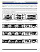
ALM26 Series models may be ordered with a choice of 8, 16, and 24 channels standard. Other channel quantities (up to 24) may be
ordered as special options. However, ALM26 Models utilizing XLR connector inputs are limited to twelve (12) or fewer channels
due to space constraints resulting from the comparatively large size of XLR connectors.
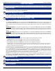
NOTE: In the model names below and throughout this manual, the unspecified channel quantity is indicated by "nn".
A = Analog
D = Digital
(none) = Phoenix (3-Pin Male)
/B = BNC (Female)
/X = XLR (3-Pin Female)
{
{
Signal
Connector
Model Option Naming Key
1st Appended Letter...........
2nd Appended
Letter.............................
NOTE: Analog models use 6-pin "mini" Phoenix connectors,
Digital models use standard 3-pin Phoenix connectors.