
User manual


ALM26 Series User Manual P/N 821644 Rev-A
6
© 2006 Wohler Technologies Inc. ALL rights reserved
TERM
TERM
TERM
TERM
AES (110 )
TERM
TERM
TERM
TERM
AES (110 )
23
24
19
20
TERM
TERM
TERM
TERM
AES (110 )
21
22
15
16
17
18
11
12
13
14
7
8
9
10
3
4
RS232
OPT
PORT 1
5
6
1
2
INTERNAL POWER
UNDERWRITERS LABS
LABEL ON SIDE
SEE POWER SUPPLY
AES
75
AES
75
AES
75
TERM
TERM
AES
75
TERM
TERM
AES
75
AES
75
AES
75
TERM
TERM
AES
75
TERM
TERM
23-24
19-20
AES
75
AES
75
AES
75
TERM
TERM
AES
75
TERM
TERM
21-22
17-18
15-16
11-12
13-14
9-10
7-8
3-4
RS232
OPT
PORT 1
5-6
1-2
INTERNAL POWER
UNDERWRITERS LABS
LABEL ON SIDE
SEE POWER SUPPLY
CH ACH A CH B
CALIB
CH B
CH ACH A CH B
CALIB
CH B
CH ACH A CH B
CALIB
CH B
CH ACH A CH B
CALIB
CH B
23-24
19-20
CH ACH A CH B
CALIB
CH B
CH ACH A CH B
CALIB
CH B
21-22 15-16 13-14 7-8
17-18 11-12 9-10 3-4
RS232
OPT
PORT 1
INTERNAL POWER
UNDERWRITERS LABS
LABEL ON SIDE
SEE POWER SUPPLY
5-6
1-2
Section 1: General Features and Specifications
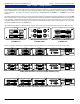
The 1U ALM26 rear panels are comprised of modular panel sections. In any given ALM26 model, from one to three of the modular
panel sections contain the audio input connectors (unused sections have blank panels), with a fourth remaining section containing the
alarm controller features. This arrangement permits mixing of different types of input modules, although such mixes are considered
special order items. The number of channels is designated by a number following the ALM26 (i.e., ALM26-24 = twenty-four
channels).
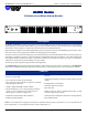
The following illustration shows three types of input panel section modules (two digital and one analog) available for use in the ALM26
Series. Analog models are referred to with an "A" appended to the standard product name and Digital (AES) models are referred to with
a "D" appended. Models featuring Phoenix connector inputs do not append any letter to the model name as these connectors are
considered standard. BNC connector inputs append a "/B" to the model name and XLR connector inputs append an "/X". See page 5
for a list of all standard models in the ALM26 series.
Please note that XLR models are limited to twelve channels (or less) due to space constraints when using the larger XLR connectors.
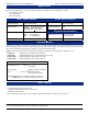
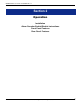
Rear Panel Configurations
Phoenix Input Modular Section
for ALM26-nnD
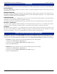
Below are examples showing three standard configurations of the ALM26 series rear panels for twenty-four channel units.
BNC Input Modular Section
for ALM26-nnD/B
ALM26-24A Rear Panel (24-Channel Analog with "mini" Phoenix Inputs)
TERM
TERM
AES (110 )
TERM
TERM
AES
75
AES
75
TERM
TERM
TERM
TERM
AES
75
AES
75
CH B
CH B
3-4
7-8
CH A
CH A
1-2
CH B
CALIB
CH A
5-6
CH B
CALIB
CH A
"Mini" Phoenix Input Modular Section
for ALM26-nnA
ALM26-24D Rear Panel (24-Channel Digital with Standard Phoenix Inputs)
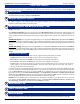
ALM26-24D/B Rear Panel (24-Channel Digital with BNC Inputs)