
User manual


ALM26 Series User Manual P/N 821644 Rev-A
9
© 2006 Wohler Technologies Inc. ALL rights reserved
Installation
Section 2: Operation
Mounting
The unit should be mounted where convenient for operating persons, ideally at approximately eye level for best visual monitoring.
Heat Dissipation
No special considerations for cooling are necessary as long as the ambient temperature inside the rack area does not exceed
approximately 40°C (104°F).
Mechanical Bracing
The chassis is securely attached to the front panel at five points along its surface, not just at the four corners of the chassis ears.
This feature will reduce or eliminate rear bracing requirements in many mobile/portable applications. The weight of internal
components is distributed fairly evenly around the unit.
Audio Connections
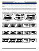
Connection of the audio feeds is straightforward. Please refer to the system interconnect block diagram on pages 22 and 23 for
clarification of the general signal paths into the ALM26 series units.
Care should be exercised to avoid mismatched cable types and other similar causes of undesired reflections in RF signal systems.
Electrical Interference
As with any audio equipment, maximum immunity from electrical interference requires the use of shielded cable; however,
satisfactory results can sometimes be obtained without it. The internal circuitry common is connected to the chassis.
AC Power
The unit's AC mains connection is via a standard IEC inlet, with safety ground connected directly to the unit's chassis. The
universal AC input (100-240VAC, 50/60Hz) switching power supply is a self-resetting sealed type, with automatic over-voltage
and over-current shutdown. There is no user-replaceable fuse in either the primary or secondary circuit.
All ALM53 Series units feature a Piezo Alarm Sounder located on the front panel (Item 1, page 10). This sounder produces an audible
alarm when any channel goes into any alarm condition. This sounder may be disabled or enabled using the instructions below. The
sounder may also be enabled and disabled with the WAC software (see Section 5.6, System Settings in the WA C manual for details).
To ENABLE the acoustic sounder in the unit, perform the following steps on the front panel:
1) Hold down the Reset All button (Item 6, page 10)
2) Press and release the Channel 3 Reset Alarm button (Item 4, page 10)
3) Release the Reset All button
To DISABLE the acoustic sounder in the unit, perform the following steps on the front panel:
1) Hold down the Reset All button (Item 6, page 10)
2) Press and release the Channel 1 Reset Alarm button (Item 4, page 10)
3) Release the Reset All button
Alarm Sounder Enable/Disable Instructions