CONFIDENCE IS EVERYTHING.
© 2010 Wohler Technologies, Inc. and PANORAMA. All rights reserved. This publication is protected by federal copyright law. No part of this publication may be copied or distributed, stored in a retrieval system, or translated into any human or computer language in any form or by any means electronic, mechanical, manual, magnetic, or otherwise, or disclosed to third parties without the express written permission of Wohler Technologies.
VAMP2 Series User Guide Introduction Overview The VAMP2 Series multi-format, multi-channel monitors are complete, exceptionally high quality stereo video/audio monitoring solutions available in a compact 2RU rack space with numerous input and output features that make these units ideal for facility-wide monitoring of analog/digital audio and video signals.
V A M P 2 S e r i e s U s e r G u id e S a f e t y I n s tr u c ti o n s Safety Instructions IMPORTANT: 1. Read, keep, and follow all of these instructions; heed all warnings. 2. Do not use this equipment near water. 3. Use only a dry cloth to clean the equipment. 4. Do not block any ventilation openings. Install only in accordance with the instructions in the section entitled, “Installation Recommendations” on page 3. 5.
VAMP2 Series User Guide I n s ta l la t i o n R e c o m me n d a t io n s Installation Recommendations Unpacking Unpack the VAMP2 Series monitor from the shipping container and inspect all components for shipping damage. If you find any damage, notify the shipping carrier for claims adjustments. Compare the shipping box contents to the packing slip. Contact Wohler’s customer support personnel about any discrepancies. (Wohler’s contact information in on the copyright page ii, of this manual).
V A M P 2 S e r i e s U s e r G u id e D e s c r ip t i o n Cable Connections Wohler recommends Beldon 8281 or Belden 1694A cables for analog video signals and Beldon 9451 cables for analog audio signals. Power Each unit comes with a standard 24VDC/3.0A internal power supply and connects an A/C mains power source (65W, 100 to 240 VAC, 50/ 60Hz) to the IEC connector provided on the rear panel of the unit.
VAMP2 Series User Guide Applications Applications The VAMP2 Series is ideally suited to provide high quality multichannel and/or digital audio and video monitoring in a very compact form. Ideal for use in VTR bays, mobile production vehicles, teleconferencing installations, multimedia systems, satellite links, cable TV facilities, and on-air radio studios.
V A M P 2 S e r i e s U s e r G u id e Features Video • 4” active matrix TFT LCD display with 4:3 aspect ratio • Auto-detection of NTSC and PAL video formats • Digital signal status indication by LEDs • Two SD-SDI (SDA model) or HD/SD-SDI (MDA model) video inputs and two CVBS video inputs with A/B switching • Converts SDI video to CVBS (composite analog) video • Monitors and de-embeds one video channel simultaneously • Re-clocked output for selected SDI source • Analog (composite) output of selected video
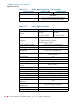
VAMP2 Series User Guide S p e ci f i c a t i o n s Specifications The VAMP2 Series monitors meet the specifications listed in Table 1–1 through Table 1–6 on page 10. Table 1–1 Audio Specifications Specification VAMP2-SDA VAMP2-MDA 2 Banks of 4 analog on DB-25 Inputs 2 Banks of 2 AES on BNC Outputs Level Meters Level Meter Scale Level Meter Mid-scale Resolution Level Meter Dynamics Peak Acoustic Output: (@ 2 ft.
V A M P 2 S e r i e s U s e r G u id e S p e c if i c a ti o n s Table 1–1 Audio Specifications (Continued) Specification Electrical Distortion Acoustic Distortion Table 1–2 VAMP2-MDA < 0.15% at any level below input threshold < 1.
VAMP2 Series User Guide S p e ci f i c a t i o n s Table 1–3 Power and Other Specifications Specification Magnetic Shielding A/C Mains Input Power Consumption Speaker Amp Power Output Dimensions Weight Table 1–4 Format SDTV, 54 SDTV, 36 SDTV, 27 SDTV, 54 SDTV, 36 SDTV, 27 Table 1–5 Format SDTV, 54 SDTV, 36 SDTV, 27 SDTV, 54 SDTV, 36 SDTV, 27 HDTV, 74.25 HDTV, 74.25 HDTV, 74.25 HDTV, 74.25 HDTV, 74.25 HDTV, 74.25 HDTV, 74.
V A M P 2 S e r i e s U s e r G u id e S p e c if i c a ti o n s Table 1–6 Level Meter Specifications Specification Level Meter Type Segment Quantity Level Meter Scale Dynamic Range Mid-scale Resolution Bar Graph Length Indication Accuracy Bar Graph 53 0 to -66 dB 66 dB 1 dB 2.22” (56.4 mm) +10 to -30 dB ± 0.2 dB -31 to -44 dB ± 0.
VAMP2 Series User Guide Front Panel Features Front Panel Features Figure 1–1 VAMP2 Series Front Panel Speaker Assign Speaker Mix Volume Level Meters Phase Channel LEDs SDI Group Color Tint LCD Video Video Source Mix Assign Speaker Select SDI Select Balance Audio Audio Source Analog/AES Select 1 & 2 Headphones Contrast Brightness Speakers • Speakers: The speaker system is comprised of two full-range speakers (left and right).
V A M P 2 S e r i e s U s e r G u id e Front Panel Features Table 1–7 Button Right Speaker Assign Mix Configuration Button Push Channel LED LED Color Speaker Assignment 1 2 3 4 5 1 2 3 4 Right Mix Amber Right • Mix (LEDs, Left and Right): When the left and/or right Speaker Assign button is pushed a fifth time, its associated Mix LED glows green to indicate that channels can be added to that speaker mix (Mix Mode) by pushing the Mix Assign Buttons located under the level meters.
VAMP2 Series User Guide Front Panel Features When CVBS 1 or 2 is selected, one of the two corresponding CVBS inputs on the rear panel is selected for monitoring. See the Audio Select button (page 14) for information about selecting audio inputs with video monitoring. Note that the selected CVBS LED will glow green when selected. • Channel Indicators (LEDs, 1 through 4): These four LEDs (1, 2, 3, and 4) indicate when the associated channel is assigned to one or both speakers.
V A M P 2 S e r i e s U s e r G u id e Front Panel Features • Headphone Jack (1/4” Connector): Select the headphone audio sources as you would for the internal speakers. When you plug in headphones, the internal or external speakers will mute. • Tint (TNT): Turn this potentiometer to adjust the color hue of the video image (for NTSC signals only). • Chroma (COL): Turn this potentiometer to adjust the color saturation of the video image.
VAMP2 Series User Guide Rear Panel Connectors • Tracks Video: This setting will monitor the AUX audio source associated with the selected CVBS video source. Table 1–8 below shows the AUX input that are associated with the CVBS inputs with this setting.
V A M P 2 S e r i e s U s e r G u id e R e a r P a n e l C o n n e ct o r s CVBS 1 or 2. See CVBS Terminator below for termination setting values. • CVBS Terminator (Four-Position DIP Switch): Termination for the CVBS (composite analog) input connectors is adjustable through the four-position DIP switch located between the two CVBS input sections (1 and 2). The switch section nearest the associated connector sets the termination for that connector (CVBS 1 = left; CVBS 2=right).
VAMP2 Series User Guide Rear Panel Connectors switch to positions 8 or 9 resets the video scaler and the audio deembedder. • Option B (Rotary Switch): This opening features a 10-position rotary switch that is reserved for future use and should be left at the factory position of 1. • Converted CVBS Out (from SDI, BNC-F): This female BNC connector outputs CVBS (composite) video encoded from the selected SDI input.
V A M P 2 S e r i e s U s e r G u id e R e a r P a n e l C o n n e ct o r s To monitor video from these inputs, set the following: • The Video Source select button to SDI, • The SDI Input select button to SDI input either (In 1 or In 2), and • The SDI Group select button to the SDI Group of choice (1, 2, 3, or 4).
VAMP2 Series User Guide Rear Panel Connectors Figure 1–3 Unbalanced AES Out from SDI HD-15 Connector Pin-Out • Balanced AES Output from SDI Input Connector (Optional DB-25): AES signals de-embedded from the selected SDI input are output from this DB-25 connector, configured for balanced connections (110 impedance). Pin-out information for the balanced DB-25 connector is shown in Figure 1–4 below.
V A M P 2 S e r i e s U s e r G u id e R e a r P a n e l C o n n e ct o r s Figure 1–5 Balanced AES In with Loop Out DB-25 Connector Pin-Out AES Input AUX 1 AUX 2 Loop-Through Output AUX 1 AUX 2 AES1 AES2 AES1 AES2 AES1 AES2 AES1 AES2 • RS-232 #1 (DB-9): This connector provides an interface for downloading the user interface, unit functionality, AES programming, setup, and diagnostic information into and out of the unit.
VAMP2 Series User Guide Rear Panel Connectors Figure 1–7 AUX 2 - AES Input Termination AUX 2, AES 1 Balanced AUX 2, AES 1 Unbalanced AUX 2, AES 2 Balanced AUX 2, AES 2 Unbalanced Up: Unterminated Down: Terminated 1 2 3 4 • AUX 1 & 2 Input 1 & 2 (on BNC): The four BNC connectors in the AUX 1 and AUX 2 input sections accept standard AES audio signals and are configured for unbalanced connections (75 impedance).
VAMP2 Series User Guide Technical Functional Overview Technical Functional Overview Figure 1–9 Metered Analog Out VAMP2-SDA Block Diagram 4 Loop-Through Balanced AES Input and Loop Output AES Input 1 AES Input 2 AES Input 1 AES Input 2 4x4 Audio Source Matrix 2 HD/SD SDI Output CVBS Video Output CVBS In 1 4 Volume Balance 2 Aux 2 AES In 2 8-Channel A/D Converter Unbalanced or Balanced AES Output From SDI SD-SDI Headphone Aux 1 AES In 2 Analog Input (Aux 1 & 2) HD/SD SDI Input 1 HD/SD SDI
VAMP2 Series User Guide T e c h n i c al F u n c ti o n al O v e r v ie w Figure 1–10 Metered Analog Out 4 Loop-Through Balanced AES Input and Loop Output AES Input 1 AES Input 2 AES Input 1 AES Input 2 4x4 Audio Source Matrix HD/SD SDI Output CVBS Video Output CVBS In 1 CVBS Loop Out 1 Headphone Aux 1 AES In 2 4 Volume Balance 2 Aux 2 AES In 2 8-Channel A/D Converter Unbalanced or Balanced AES Output From SDI SD-SDI or HD-SDI 1 2 3 4 2 Analog Input (Aux 1 & 2) HD/SD SDI Input 1 HD/SD S
V A M P 2 S e r i e s U s e r G u id e Technical Functional Overview 24 © 2 01 0 Wo h le r Te ch n ol og ie s , I n c . A l l r i g h t s r e s e rve d .