
User manual


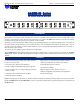


ALARM-24 Series User Manual P/N 821542 Rev-A
10
© 2003 Wohler Technologies Inc. ALL rights reserved
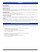
Please refer to the example in Figure-2a on the following page to familiarize yourself with the front panel features of the ALARM-
24 Series units. The following sections describe these functions and are referenced, by number, to Figure-2a.
Section 2: Operation
Front Panel Features
1
2
3
4
5
6
7
Alarm Sounder
The Piezo Alarm Sounder produces an audible alarm when the the alarm threshold has been exceeded. See page 9 for
instructions for how to disable or enable the Alarm Sounder.
Loss (of Audio) Indication LED
This RED LED lights up to indicate that the loss of audio alarm threshold has been exceeded in the associated channel.
Channel Reset Button
ALARM-24xS/x: For the stereo product, this momentary push-button resets the alarm for the associated channel pair.
ALARM-24xM/x: For the mono product, this momentary push-button resets the alarm only for each single channel.
Phase/Polarity Reversal Indication LED OR Channel Reset Button
ALARM-24xS/x: For the stereo product, this is a YELLOW LED, which lights up to indicate that the phase alarm threshold
has been exceeded in each associated channel pair.
ALARM-24xM/x: For the mono product, this is a Channel Reset Button (see Item 4, above), which resets the alarm for
each single channel.
Clipping Indication LED
This RED LED lights up to indicate that the audio clipping alarm threshold has been exceeded in the associated channel.
Power Indication LED
This GREEN LED lights up to indicate the ALARM-24 model is connected to operational mains power.
Reset All Push-Button
This momentary push-button simultaneously resets the alarm for ALL the channels in the unit.