
User guide


© 2010 Wohler Technologies, Inc. All rights reserved.
12
AMP V Series User Guide
Front Panel Controls
AMP2-VSDA-Specific Controls
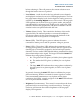
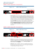
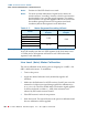
Figure 1–4 AMP2-VSDA Front Panel
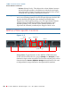
• Analog/Digital Select (Toggle Switch): This two position switch
selects between two primary input sources, analog or digital. When
this toggle switch is set to analog, the unit will monitor the signals
as input on the rear panel Analog In phoenix connectors. When
this toggle switch is set to digital, the unit will monitor whichever
source is selected by the AES/SDI switch.
• AES/SDI (Toggle Switch): This two position toggle switch allows
the operator to choose between the two digital input sources; SDI or
AES. When this toggle switch is set to AES, the unit will monitor the
AES signals as input on the AES In BNC or XLR connectors (In 1
and
In 2) on the rear panel. When this toggle switch is set to SDI,
the unit will de-embed and monitor the SDI signals as input on the
SDI In BNC connector on the rear panel.
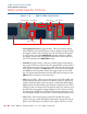
• AES (1 & 2, LEDs): These two bi-color green/red LEDs (AES1 and
AES2) indicate the input presence and status of the two AES input
signals. Each LED glows green as long as a valid AES/EBU digital
datastream for the associated input channel is being received. Each
LED glows red to indicate errors in signal reception or data errors (if
the data has been tagged as inappropriate for conversion to analog
by having the validity bit set). These LEDs function whether or not
the AES digital signals are selected for monitoring through the unit.
• SDI (LED): This bi-color (green/red) LED, labeled SDI, glows
green as long as a valid SDI digital datastream is being received. It
glows red if TSR errors are present in the signal. If there is no SDI
Speakers
Power
Speaker Assign
Headphones
Phase
Analog/Digital
AES/SDI
Balance
AES 1 & 2
Volume
Brightness
SDI
Level Meters