
User guide

© 2010 Wohler Technologies, Inc. All rights reserved.
19
AMP V Series User Guide
Line Level Calibration Instructions
6. Place DIP section 1 in the up position and return unit to service.
7. Only one auto-calibration attempt may be made for each cycling of
AC power to the unit. Once the Line Level Calibration DIP switch
has been placed in the CAL position, it is necessary to cycle the
power before that DIP switch will be functional again, even if a
calibration attempt was unsuccessful.
If you want to calibrate again, turn off the power to the unit and repeat
steps 1 through 6.
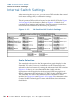
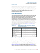
Reference Level
DIP switch sections 2 and 3 determine the Reference Level, which
adjusts the level of the input signal and the resultant level displayed on
the LED bargraphs. Factory setting is +4 dB. See DIP switch diagram
below for settings.
Bar Graph Display Mode
DIP switch sections 4 and 5 determine how peak levels are displayed
for the associated meters on the front panel.
The four possible settings are:
• VU Only,
• VU-PPM Floating Segment,
• PPM Only, and
• PPM-PPM Floating Segment.
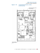
The VU Only selection has a VU floating segment when a Peak Hold
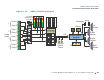
value is selected using the Internal 10-Position DIP Switch Module (see
Figure 1–12 on page 20). The factory default setting is VU-PPM Floating
Segment.