
User guide

821024: AMP1-DA/106 User Guide
© 2011 Wohler Technologies, Inc. All rights reserved.
14
AMP1-DA/106 User Guide
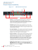
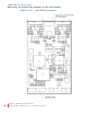
Rear Panel 6-Position DIP Settings for the Level Meters
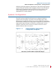
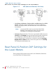
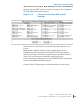
Figure 1–7 XLR (Male and Female) Pin-Outs)
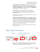
• Level Meter Calibration, Display Mode, and Reference Level DIP
Switch: This DIP switch sets the Line Level (Auto) Calibration
feature, the Display Mode, and the Reference Level for the Audio
Level Meters.
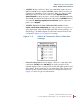
• Analog In (Right and Left): These two 3-pin female XLR connectors
(
CH.A(L) and CH.B(R)) accept standard analog audio signals and
are configured for balanced, 40k Ω connections. The unit will
monitor signals input on these two connectors when the Analog/
Digital Source Select
switch on the front panel is set to Analog.
For XLR pinout information see .
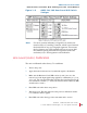
Rear Panel 6-Position DIP Settings for
the Level Meters
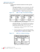
This 6-position DIP switch sets the Line Level Calibration, Reference
Level, and PPM/VU Display Mode.
Female
Male
Note:
An internal DIP switch sets the Peak Hold, PPM
Ballistics, and Alternative Scales. See page 19 for
information on setting these parameters.