
User guide


© 2009 Wohler Technologies, Inc. All rights reserved.
15
AMP1A Series User Guide
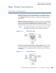
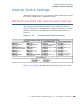
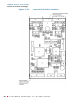
Rear Panel Connectors
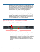
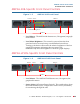
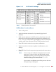
Figure 1–9 DIP Switch Settings
Calibration Instructions
1. Turn on the power.
2. Apply the desired reference level (nominal 0) signal to all
channels.
3. Make sure the reference level DIP sections (2 and 3) are set to the
nearest level of the input signal being applied for calibration (i.e.,
0, +4, +6 or +8). Verify that the signal applied to all four channels is
within ± 4 dB of the reference level set in DIP switches 2 and 3.
4. Place DIP Switch 1 in the down position (calibration).
5. Wait 10 seconds for the unit to update its calibration to your
settings.
6. Place DIP Switch 1 in the up position (operation) and return unit to
service.
Note:
Switch position 6 is not used.
Note:
You can only auto-calibrate the monitor once for each
power cycle. Once you have put DIP Switch 1 in the
calibration position, you must cycle the power before
that DIP switch will be functional again, even if a
calibration attempt was unsuccessful.
If you want to re-calibrate, turn off the power to the unit
and repeat steps 1 through 6.