
User guide


© 2009 Wohler Technologies, Inc. All rights reserved.
17
AMP1A Series User Guide
Internal Switch Settings
Internal Switch Settings
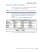
After removing the top cover, you can access DIP switches that control
level meter settings and/or calibration settings.
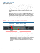
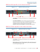
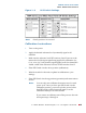
AMP1A-30 and AMP1-106 Internal Switch Settings
This 10-position DIP module is located on the 919174 PCB. Refer to
Figure 1–12 below for a complete list of settings and functions. (Switch
positions 1 and 10 are not used and should be left at the factory set
position.)
Figure 1–12 0-Position DIP Switch Settings
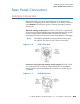
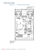
Figure 1–13 on page 18 illustrates the DIP switch location on the PCB.