
User guide

© 2009 Wohler Technologies, Inc. All rights reserved.
21
AMP1A Series User Guide
Internal Switch Settings
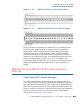
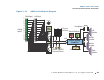
Figure 1–16 AMP1-30 Phase Correlation Labels
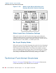
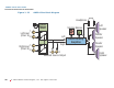
Figure 1–17 AMP1A-106 Phase Correlation Labels
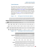
Positive amounts of correlation are indicated by an ascending amber
bar in the lower (right channel) bar graph; negative correlation is
shown when a red bar ascends in the top (left channel) bar graph.
While the audio level in both channels is high enough, the phase
correlation indication occupies the bottom 13 segments of both bar
graphs of a 30-segment stereo pair. One additional segment above the
active correlation region is always off, to serve as a marker. The
correlation display is visible only so long as the VU audio level is above
this blank segment (fourteenth segment up on the 30-segment bar
graph).
AMP1A Plus and AMP1A-LP10S Internal Switch
Settings
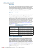
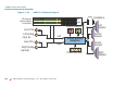
Level Meter DIP Switch Settings
Two DIP switch modules, accessed through an opening in the top
cover, allow the user to set the bar graph display mode and meter input
gain calibration independently for each of the two bar graph displays.
There are four sections (S1, S2, S3, S4) on each DIP switch module. The
first two sections (S1, S2) are for setting the meter input gain calibration
and the second two sections (S3, S4) are for setting the bar graph
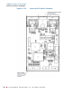
display mode. See Figure 1–18 on page 22.