RMT-173 Series • RMT-173-RM • RMT-173-TT Dual Input, LCD, Multi-Viewer Audio/ Video Monitors User Guide Part Number 821100, Revision A
© 2013 Wohler Technologies, Inc. All rights reserved. This publication is protected by federal copyright law. No part of this publication may be copied or distributed, stored in a retrieval system, or translated into any human or computer language in any form or by any means electronic, mechanical, manual, magnetic, or otherwise, or disclosed to third parties without the express written permission of Wohler Technologies. Reproduction Licensed users and authorized distributors of Wohler Technologies, Inc.
RMT-173 Series Introduction Overview The RMT-173 Series dual input, LCD video monitors are highperformance, professional LCD monitors that support advanced 12-bit digital processing technology with 3D comb filter and de-interlace, accurate scaling engine, GAMMA correction and color temperature adjustments to achieve the best possible image display. The RMT-173 Series supports 2-channel 3G/HD/SD-SDI, Y/C, component, and CVBS signal inputs as well as a single HDMI signal input.
RM T - 1 73 Se r ie s Sa f e t y Safety Important Safety Instructions IMPORTANT: 1. Read, keep, and follow all of these instructions; heed all warnings. 2. Do not use this equipment near water, rain or moisture. 3. Use only a dry cloth to clean the equipment. 4. Do not install near any heat source such as a radiator, heat register, amplifier, or stove. 5. Do not attempt to plug the unit into a two-blade outlet (with only two prongs of equal width).
RMT-173 Series I n s t a l la t io n R e c om m e n d a t io n s Safety Symbols WARNING: The symbol to the left warns of electric shock hazard inside the unit. Disconnect the power cord before removing access panels when installing upgrades. Only qualified service personnel are to operate the equipment with covers removed, and are to exercise caution to avoid personal injury.
RM T - 1 73 Se r ie s U n p a ck in g a n d I n s t a ll a t io n Note: HDMI 1.3 or 1.4 cable lengths of 2m (6 feet) are guaranteed to work well. Four meters (12 feet) lengths of high quality cable should work well enough, but is not guaranteed for all situations. Longer HDMI cables often degrade signal quality. Active extender transmitter/receiver pairs can be used to cover long distances.
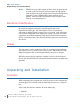
RMT-173 Series U n p a c k in g a nd I n s t a ll a t io n • Adapter (12 VDC) • Power cord • User guide CDROM • Warranty card Mounting The RMT-173 Series monitors come standard with either a table top base (RMT-173-TT) or rack ears (RMT-173-RM). A standard VESA 100 pattern accommodates other user-supplied mountings, such as for walls. To install the table-top base, refer to Figure 1–1 and the instructions that follow. Refer to the instructions included with other mounts when used.
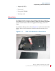
RM T - 1 73 Se r ie s U n p a ck in g a n d I n s t a ll a t io n 1. Place the monitor face down on a smooth surface and, as shown in Figure 1–1, use a screwdriver and the supplied round head screws to fasten the bracket to the back of the monitor. Figure 1–2 8 21 10 0 : 6 RMT-173-RM Base Installation 2. Next, again using a screwdriver, attach the base to the bracket, with the supplied flat head screws, as shown in Figure 1–2. 3. Place the monitor upright on a solid static-free surface. 4.
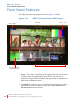
RMT-173 Series F ea t u r e s Features The RMT-173 Series monitors provide the following features: • Multi-format analog and digital audio signals • Adjustment of the parameters for each channel • High-quality waveform and/or vector monitoring • Embedded SDI or stereo analog audio through speakers or headphones • Audio bar graph meters, up to sixteen • Stereo analog audio line output of selected channel • Area, safety, and center markers • Closed captions for CVBS • Pre-set or user-adjustable color tempera
RM T - 1 73 Se r ie s F r o nt P a n el F e a t u r e s Front Panel Features The following feature descriptions refer to Figure 1–3 below. Figure 1–3 RMT-173 Front Panel (PIP Layout) Status - Sub LED Tally Status - Main Audio Level Meters Vertical (Bot Left) Buttons • Status: The status is displayed in the upper left corner for the main window and in the upper right corner for the sub-window. It includes the input channel number and signal format. Operation is defined in the DISPLAY menu.
RMT-173 Series F r o n t P a n el F ea t u r e s • IMD: The 16 characters of the in-monitor display (IMD) can be displayed in red, green, yellow, or white. OSD CONFIG IMD DISPLAY, IMD COLOR, and IMD CHAR define the static operation. The IMD menu defines the dynamic IMD and OSD tally operations. • Timecode: The display format for the timecode is HH: MM: SS: FF. In the event no timecode is available, the monitor will display --:--:--:--.
RM T - 1 73 Se r ie s F r o nt P a n el F e a t u r e s • PBP Function: In PIP or PBP screen modes, the SUB window displays the second video input, as defined in the Config Menu on page 22 or the Function Key Menu on page 25.
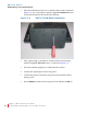
RMT-173 Series R e a r P a n el F ea t u r e s Rear Panel Features Figure 1–5 RMT-173 Complete Rear Panel Figure 1–6 RMT-173 Rear Panel - Lower Right • DC IN (jack): Accepts power plug from the included 12 VDC power adapter. • Power (Rocker Switch): Turns power to the monitor on (1) or off (0). 8 21 10 0: R MT-1 73 S e r ie s U se r G u id e © 20 13 Wo hl e r Te c hn ol og i e s , In c . A l l r ig h ts re se rv ed .
RM T - 1 73 Se r ie s Re a r Pa n e l F e a t u r es Figure 1–7 RMT-173 Rear Panel - Upper Left SDI Video Inputs (2 BNC) and SDI Outputs (2 BNC): These inputs and outputs receive and regenerate the 3G/HD/SD-SDI signals. HDMI IN: Type A HDMI jack accepts non-DHCP HDMI signals in standard broadcast video formats, It can also accept similar DVI-D resolutions with an adaptor (not supplied). Ethernet (RJ-45): Network interface for upgrades and dynamic tally/ UMD.
RMT-173 Series R e a r P a n el F ea t u r e s Figure 1–8 RMT-173 Rear Panel - Lower Left • Line 1 Input and Output (2 BNC): CVBS composite analog video. • Line 2 Inputs and Outputs: CVBS/Y (2 BNC), Pb/C (2 BNC), Pr (2 BNC), analog composite, S-video, and component video. • Audio Inputs (4 RCA) and Outputs (2 RCA): Each input pair (one for each channel) accepts standard analog audio. Output is from last (video) channel selected as heard from the speakers/ headphones.
RM T - 1 73 Se r ie s Re a r Pa n e l F e a t u r es Table 1–1 GPI Pin Out Pin 1 2 3 4 5 6 7 8 Figure 1–9 Function GPI 1 GPI 2 GPI 3 GPI 4 GPI 5 GPI 6 NC GND RJ45 Connector Pin Map . Table 1–2 Pin 1, 2 3 4 5 6 7, 8 8 21 10 0 : 14 RS485 Pin Out RS485 In Terminal Signal GND TxRx+ RxTx+ NC RM T-1 73 S e r ie s U s e r G ui d e © 2 01 3 Woh le r Te ch no lo g ie s, Inc . A ll ri g ht s re s e r v ed .
RMT-173 Series U s i ng t h e M e n u S y s t e m Using the Menu System Configuring the RMT-173 Series monitors is accomplished in the Menu system . Each of the menus is explained on this and the following pages. 1. Press the MENU button to display the menu. 2. Use the Up and Down buttons to navigate through the submenus.
RM T - 1 73 Se r ie s U s in g t h e M en u S y s t e m Status Menu Note that none of the options displayed on the STATUS menu are editable. Table 1–3 Status Menu Parameters Default Value Domain Range INPUT (Main) FORMAT COLOR TEMP SCAN MODE FAST MODE MODEL Display only; Non-selectable. The values vary depending on input signal type and configuration settings.
RMT-173 Series U s i ng t h e M e n u S y s t e m Marker Menu Important: MARKER is disabled when SCAN mode is NATIVE, or when the input signal is DVI or VGA. Table 1–5 Marker Menu Parameters MARKER Default Value OFF Domain Range All markers ON (enabled) or OFF (disabled) Select the area marker aspect ratio to be displayed. Note: the aspect ratio of the current image will not appear in this list. • OFF: turns area marker off • 4:3 AREA MARKER OFF • 16:9 • 15:9 • 14:9 • 13:9 • 16:9 • 1.85:1 • 2.
RM T - 1 73 Se r ie s U s in g t h e M en u S y s t e m Table 1–5 Marker Menu (Continued) Default Value Parameters Domain Range Sets the luminance (white level or brightness) to display safety, center, and area marker line, where: MARKER LEVEL 1 • 1 = 100% • 2 = 75% • 3 = 50% Sets the area marker matte transparency, where: MARKER MAT OFF • OFF = Normal background, use line for area marker edge only • HALF = 50% Background brightness CROSS HATCH 8 21 10 0 : 18 OFF RM T-1 73 S e r ie s U s e r
RMT-173 Series U s i ng t h e M e n u S y s t e m Audio Menu The menu sets up the audio sources for each channel according to the last video input selected. Speakers and the analog Audio Output follow the selection accordingly.
RM T - 1 73 Se r ie s U s in g t h e M en u S y s t e m Table 1–6 Audio Menu (Continued) Parameters Default Value Domain Range Select the audio meters to display: • OFF • CH1-2 • G1 (Group 1: 4 channels: 1-4) • G2 (Group 2: 4 channels: 5-8) • G3 (Group 3: 4 channels: 9-12) • G4 (Group 4: 4 channels: 13-16) • G1+G2 (Groups 1 & 2: 8 channels: 1-8) METER SELECT G1-4 • G1+G3 (Groups 1 & 3: 8 channels: 1-4, 9-12) • G1+G4 (Groups 1 & 4: 8 channels: 1-8, 13-16) • G2+G3 (Groups 2 & 3: 8 channels: 5-12) • G2
RMT-173 Series U s i ng t h e M e n u S y s t e m Table 1–6 Audio Menu (Continued) Default Value Parameters -20dB REF LEVEL -10dB OVER LEVEL Domain Range Select the reference level: -20dB or -18dB Select the overload level: • -10dB • -8dB • -6dB • -4dB • -2dB Display Menu Table 1–7 Display Menu Default Value Parameters Domain Range STATUS DISPLAY OFF OFF/AUTO/ON AFD DISPLAY OFF OFF/ON • OFF WAVEFORM TYPE VECT100 • LINE WAVE • WAVEFORM • VECT75 • VECT100 • MODE 1 (WF +
RM T - 1 73 Se r ie s U s in g t h e M en u S y s t e m Table 1–7 Display Menu (Continued) Default Value Parameters WFM POS LEFT TIMECODE OFF Domain Range • LEFT • • RIGHT VITC • LTC • D-VITC • OFF Closed Caption Menu Table 1–8 Parameters Closed Caption Menu Default Value CLOSED CAPTION CC1 SDI CC LOG ON Domain Range • CC1 • CC2 • CC3 • CC4 • TEXT1 • TEXT2 • TEXT3 • TEXT4 • OFF ON/OFF Config Menu Table 1–9 Parameters 8 21 10 0 : 22 Config Menu Default Value FAST
RMT-173 Series U s i ng t h e M e n u S y s t e m Table 1–9 Config Menu (Continued) Default Value Parameters Domain Range SUB IN TYPE OFF OFF/PBP/PIP SUB IN SELECT SDI1 INPUTS PIP SIZE SMALL • SMALL/LARGE PIP POSITION • • BOT RIGHT • • BACKLIGHT 15 0 to 30 AUTO STANDBY OFF ON/OFF APERTURE 0 0 to 24 LOCK NUMBER --- 8 characters (factory setup) • ENGLISH LANGUAGE ENGLISH • TOP RIGHT TOP LEFT BOT RIGHT BOT LEFT CHINESE Color Temp Menu Important: To make custom modifications to
RM T - 1 73 Se r ie s U s in g t h e M en u S y s t e m Table 1–10 Parameters RED BIAS GREEN BIAS BLUE BIAS COPY FROM RESET 8 21 10 0 : 24 Color Temp Menu (Continued) Default Value Presets Factory Calibrated Domain Range 0 to 63 When USER1 or USER 2 is selected, COPY FROM will copy one of the --standard color temperatures to be custom modified. Resets User gain and bias to their factory defaults. RM T-1 73 S e r ie s U s e r G ui d e © 2 01 3 Woh le r Te ch no lo g ie s, Inc .
RMT-173 Series U s i ng t h e M e n u S y s t e m Function Key Menu This menu lets you customize what you need each function key to do. Table 1–11 Parameters F1 BUTTON Function Key Menu Default Value AUDIO METER Domain Range Select the function to assign to the function button: • SCAN: Enables or disables display. • NATIVE F2 BUTTON NATIVE • ASPECT: Toggles between 4:3 and 16:9 scaling (SD only).
RM T - 1 73 Se r ie s U s in g t h e M en u S y s t e m GPI Menu Table 1–12 Parameters GPI 1 GPI 2 GPI 3 GPI 4 GPI 5 GPI 6 8 21 10 0 : 26 GPI Menu Default Value TALLY GREEN TALLY RED NATIVE BLUE ONLY MONO H/V DELAY RM T-1 73 S e r ie s U s e r G ui d e © 2 01 3 Woh le r Te ch no lo g ie s, Inc . A ll ri g ht s re s e r v ed . Domain Range Select the function that each GPI will control.
RMT-173 Series U s i ng t h e M e n u S y s t e m IMD Menu Table 1–13 IMD Menu Default Value Parameters IMD DISPLAY ON Domain Range ON = Displays OFF = Does not display Select the color in which to display the IMD text: • RED IMD COLOR RED • GREEN • YELLOW • WHITE The IMD text can contain up to 16 characters including all letters, numbers, and some symbols. Select the IMD protocol you want to use: IMD CHARACTER IMD PROTOCOL LOCAL • LOCAL • TSL3.1 • TSL4.0 • TSL5.
RM T - 1 73 Se r ie s U s in g t h e M en u S y s t e m Table 1–13 IMD Menu Parameters Default Value Domain Range Select the communications baud rate: BAUD RATE 9600 • 2400 • 4800 • 9600 • 19200 • 38400 • 57600 • 115200 LED TALLY ON ON/OFF Select the OSD tally mode: • RG: Red/Green OSD TALLY MODE RG • GR: Green/Red • RGY: Red/Green/Yellow • OFF: No OSD Tally Select the IMD tally mode: • T1 • T2 • T1T2 IMD TALLY MODE T1 • T2T1 • T1• T2• T1T2• T2T1Select the LED/OSD tally source.
RMT-173 Series S p e c if ic a t io n s Key Inhibit Menu Key Inhibit Menu Table 1–14 Parameters Key Inhibit Menu Default Value Domain Range • OFF = Does not inhibit keys KEY INHIBIT OFF • ON = Inhibits all keys except POWER and MENU (to make setup changes) Specifications The general specifications of the RMT-173 Series monitors are listed in Table 1–15 below.
RM T - 1 73 Se r ie s Sp e ci fi ca t io n s Table 1–16 below lists the I/O specifications. Table 1–16 RMT-173 I/O Specifications Specification RMT-173 Values • 6 BNCs: CVBS, S-Video, YPbPr, 3G/ HD/SD-SDI (supports embedded audio) Video Inputs • HDMI 6 BNCs: Loop out of BNC In 4 RCAs: Analog stereo for EXT sources 2 RCAs: Analog stereo (monitoring, same as speakers) Video Outputs Audio Inputs Audio Outputs Table 1–17 below distinguishes each of the RMT-173 models.
RMT-173 Series S p e c if ic a t io n s Table 1–18 RMT-173 CVBS I/O Specifications Specification Differential Gain Differential Phase RMT-173 Values < 1% < 1.5° Table 1–19 below lists the specifications for SDI inputs.
RM T - 1 73 Se r ie s Te c h ni c al F un c t io n O v e r v i ew Technical Function Overview Figure 1–10 below illustrates the overall functionality of the RMT-173 Series monitors. Figure 1–10 8 21 10 0 : 32 RMT-173 Block Diagram RM T-1 73 S e r ie s U s e r G ui d e © 2 01 3 Woh le r Te ch no lo g ie s, Inc . A ll ri g ht s re s e r v ed .