INSTALLATION GUIDE Built-In Refrigeration
Contents Important Note Built-In Refrigeration . . . . . . . . . . . . . . . . . . . . . . . . . . . . . 3 To ensure the safe and efficient installation of Sub-Zero equipment, please take note of the following types of highlighted information throughout this guide: Model Specifications . . . . . . . . . . . . . . . . . . . . . . . . . . . . 4 Site Preparation . . . . . . . . . . . . . . . . . . . . . . . . . . . . . . . . . 8 Built-In Installation . . . . . . . . . . . . . . . . . . . . . . . . . . . .
Built-In Refrigeration 3 subzero.com/specs Sub-Zero Built-In Refrigeration Before You Start The importance of the installation of the Sub-Zero built-in unit cannot be overemphasized. Installation should be done by a qualified installer. Make sure that the actual equipment that was shipped to you matches the design you are expecting to install. The Sub-Zero built-in line offers the following design alternatives: framed, overlay, flush inset and stainless steel models.
Model Specifications 4 Specifications Overall Dimensions BUILT-IN MODELS ALL REFRIGERATOR / ALL FREEZER MODELS Interior Capacity R cu ft (L) F cu ft (L) 36" (914) 24" (610) ALL REFRIGERATOR / ALL FREEZER MODELS BI-36R BI-36RG BI-36F 23.4 (663) 23.2 (657) 22.8 (646) OVER-AND-UNDER MODELS BI-30U BI-30UG BI-36U BI-36UG 13.0 (368) 13.0 (368) 16.2 (459) 16.1 (456) 4.1 (116) 4.1 (116) 5.3 (150) 5.
Model Specifications 5 subzero.
Model Specifications 6 Overall Dimensions SIDE-BY-SIDE MODELS 36" (914) 24" (610) 42" (1067) 24" (610) 84" 84" (2134) (2134) 73 3/4" 73 3/4" (1873) (1873) HEIGHT DIMENSIONS ± 1/2" (13) 4" (102) HEIGHT DIMENSIONS ± 1/2" (13) 23 7/8" (606) 4" (102) 23 7/8" 23 7/8" (606) (606) 81/2" 101/4" 8 3/4" 12 1/2" (216) (260) (222) (318) 221/4" 26 1/4" (565) (668) 2 3/8" (60) 2 3/8" (60) MODEL BI-36S Overall dimensions are based on stainless steel models.
Model Specifications 7 subzero.
Site Preparation 8 Opening Dimensions STANDARD INSTALLATION TOP VIEW 24" (610) OPENING DEPTH 24" (610) OPENING DEPTH 83 3/4" A (2127) OPENING HEIGHT OPENING WIDTH SIDE VIEW FRONT VIEW Opening Width A BI-36R, BI-36RG and BI-36F 35 1/2" BI-30U and BI-30UG 29 1/2" (746) BI-36U and BI-36UG 35 1/2" BI-36S 35 1/2" (902) (902) (902) BI-42S, BI-42SID and BI-42SD 411/2" (1054) BI-48S, BI-48SID and BI-48SD 47 1/2" (1206) IMPORTANT NOTE: If two units are installed side by side, refer to page
Site Preparation 9 subzero.
Site Preparation 10 Dual Installation Opening Dimensions STANDARD INSTALLATION TOP VIEW 24" (610) OPENING DEPTH 24" (610) OPENING DEPTH 83 3/4" A (2127) OPENING HEIGHT OPENING WIDTH SIDE VIEW FRONT VIEW Opening Widths A Two 30" (762) Models 59 3/4" 30" (762) and 36" (914) Models 65 3/4" (1670) Two 36" (914) Models 71 3/4" (1518) (1822) IMPORTANT NOTE: A dual installation kit will be required for this installation. Stainless steel models are ready to install out of the box.
Site Preparation 11 subzero.
Site Preparation 12 Site Preparation Electrical Requirements Make sure that the finished rough opening where the built-in unit is being installed is properly prepared. Refer to the overall dimensions and installation specifications for your specific model. These specifications are identical for the framed, overlay and stainless steel applications. Installation specifications are different for the flush inset application, whether you are using custom panels or Sub-Zero accessory flush inset panels.
Site Preparation 13 subzero.com/specs Plumbing Requirements All built-in models with an automatic ice maker feature a water filtration system that supplies filtered water to the ice maker and water dispenser (dispenser models). The water supply line should be located within the shaded area shown in the illustrations. The water supply line should be connected to the house supply with an easily accessible shut-off valve between the supply and the unit. Do not use self-piercing valves.
Site Preparation 14 Anti-Tip Bracket Installation To prevent the unit from tipping forward and provide a stable installation, the unit must be secured in place with the anti-tip brackets provided. IMPORTANT NOTE: Placement of the anti-tip brackets is critical to a stable installation. Failure to properly position the anti-tip brackets will prevent them from engaging the unit.
Site Preparation 15 subzero.com/specs Anti-Tip Bracket Installation WOOD FLOOR APPLICATIONS INSTALL CONCRETE WEDGE ANCHORS: After properly locating the anti-tip brackets in the rough opening, drill pilot holes 3/16" (5) diameter maximum in the wall studs or wall plate. Use the #12 x 2 1/2" PH pan HD zinc screws and #12 flat washers to secure the brackets in place. Make sure the screws penetrate through the flooring material and into wall studs or wall plate a minimum of 3/4" (19).
Built-In Installation 16 Unpack the Unit Grille Removal Uncrate the built-in unit and inspect for any damages. Remove the wood base and discard the shipping bolts and brackets that hold the wood base to the bottom of the unit. Remove and discard all packing materials. In order to prevent damage to the grille and to access the power cord, the top grille assembly should be removed prior to moving the unit. IMPORTANT NOTE: Do not discard the kickplate, anti-tip brackets and hardware.
Built-In Installation 17 subzero.com/specs Position the Unit Before moving the built-in unit into position, secure door(s) closed and protect any finished flooring. Use an appliance dolly to move the unit near the rough opening. Each built-in unit is equipped with rollers, so it can be moved into position more easily. If possible, keep the door(s) closed until the unit is properly anchored. The rear levelers must be in their lowest position in order to roll the unit back into the rough opening.
Built-In Installation 18 Level the Unit Door Adjustment Once the unit is in position, extend the front leveling legs down by turning the legs clockwise to adjust the height. The rear height adjustment can be made from the front of the base. Use a 3/8" socket to adjust the rear rollers. Turn the 3/8" hex bolt clockwise to raise the unit or counterclockwise to lower it. Refer to the illustration below for location of the rear roller base adjustment.
Built-In Installation 19 subzero.com/specs Door Adjustment Panel Installation DOOR HEIGHT ADJUSTMENT If your customer has ordered either a framed or overlay model, you will be installing door panel(s) to give the unit the custom Sub-Zero look. Before you begin installing panels, refer to the panel specifications for framed, overlay or flush inset applications on pages 22–34, and make sure you are working with the panel design called for in your installation.
Built-In Installation 20 Complete the Installation ANCHORING INSTALL KICKPLATE After door and side panels have been installed, the unit has been leveled and door adjustment completed, anchor the built-in unit to the opening. This will assure a proper fit and a secure installation. Make sure the drain pan is in the proper position before installing the kickplate. To install, screw the kickplate to brackets attached to the inside surface of each roller base. Refer to the illustration below.
Built-In Installation 21 subzero.com/specs Water Filtration System Air Purification System WATER FILTER BYPASS MODE All Sub-Zero built-in units, except model BI-36F, come with an advanced air purification system. A factory installed air purification cartridge is located inside the refrigerator section, on the right-hand side of the back wall. For information regarding use and removal of this cartridge, refer to the built-in use & care guide provided with the unit.
Panel Installation 22 Framed Panels If your customer has chosen a framed design application, make sure that the panels you are about to install match dimensions listed in the framed panel specifications on pages 24–25. Additional panel design information can be found in the Sub-Zero design guide and on our website, subzero.com.
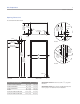
Panel Installation 23 subzero.com/specs Framed Panels To install framed panels, the door handle(s) must be removed. To install framed panels, first remove the door trim molding. For side-by-side models and the upper door for over-and-under models, insert a screwdriver tip into the top corner slot on the handle side and pop out the trim molding. Refer to the illustration below.
Panel Installation 24 Framed Panel Specifications A H A A A H H A A H A H H B W BI-36R / BI-36F W W BI-36RG BI-30U / BI-36U Models BI-36R, BI-36RG and BI-36F REFRIGERATOR/FREEZER Door Panel BI-36RG W BI-30UG / BI-36UG Models BI-30U and BI-30UG W H 35 3/4" (908) 69 9/16" (1767) W H Window Cut-Out 25 1/2" (648) 54 1/16" (1373) A B Cut-Out Location 5 3/16" (132) 10 5/16" (262) REFRIGERATOR Door Panel FREEZER Drawer Panel BI-30UG Window Cut-Out W H 29 3/4" (756) 49
Panel Installation 25 subzero.
Panel Installation 26 Overlay Panels If your customer has chosen an overlay design application, make sure that the panels you are about to install match dimensions listed in the overlay panel specifications on pages 28–29. Additional panel design information can be found in the Sub-Zero design guide and on our website, subzero.com. IMPORTANT NOTE: The size of the overlay panel is critical. It must fit over the door frame. Also, do not exceed the maximum per panel weight for your specific model.
Panel Installation 27 subzero.com/specs Overlay Panels MODELS BI-42SD AND BI-48SD GRILLE PANEL ASSEMBLY The dispenser area of models BI-42SD and BI-48SD has been engineered to enable the use of the overlay or flush inset panel application. Installing overlay or flush inset panels for these models is the same procedure as for other built-in models. The refrigerator door panel will need to accommodate a cut-out for the glasswell bezel. Remove the grille panel assembly as described on page 16.
Panel Installation 28 Overlay Panel Specifications H H H H A H A A A H H A A H A H H B W BI-36R / BI-36F W W BI-30U / BI-36U BI-36RG Overlay Panel Spacer Panel Backer Panel GRILLE Overlay Panel Spacer Panel Backer Panel BI-36RG W H 36" (914) 35 1/8" (892) 35 3/4" (908) 69 3/4" (1772) 68 15/16" (1751) 69 9/16" (1767) W H 36" (914) 35 1/8" (892) 35 3/4" (908) 9 1/4" (235)* 8 5/16" (211) 8 15/16" (227) W H Window Cut-Out 25 1/2" (648) 54 1/8" (1375) A B Cut-Out Locatio
Panel Installation 29 subzero.
Panel Installation 30 Flush Inset Panels If your customer has chosen the flush inset panel application, make sure that the panels you are about to install match dimensions listed in the flush inset panel specifications on pages 32–33. Additional panel design information can be found in the Sub-Zero design guide and on our website, subzero.com. Sub-Zero allows a 1/4" (6) space to slide the backing material into place in the frame.
Panel Installation 31 subzero.com/specs Flush Inset Panels Install the handle hardware before inserting the panel. Sub-Zero recommends using larger D-style pulls. The use of small, one-piece knobs is not recommended. If you use screws with thick heads, you will need to countersink the screws into the backer panel before sliding the assembly into place. Slide the panel into the frame on the door. With the panel in position, replace the frame end.
Panel Installation 32 Flush Inset Panel Specifications H H H H A H B A A H H A A H B H H B W BI-36R / BI-36F W W BI-30U / BI-36U BI-36RG Models BI-36R, BI-36RG and BI-36F REFRIGERATOR / FREEZER Flush Inset Panel Spacer Panel Backer Panel GRILLE Flush Inset Panel Spacer Panel Backer Panel BI-36RG H 37" (940) 35 1/8" (892) 35 3/4" (908) 69 3/4" (1772) 68 15/16" (1751) 69 9/16" (1767) W H 37" (940) 35 1/8" (892) 35 3/4" (908) 9 1/4" (235) 8 5/16" (211) 8 15/16" (227) W H 25
Panel Installation 33 subzero.
Panel Installation 34 C 5 Flush Inset Panels Illustrations A–F provide panel offsets and reveals for all D the built-in models in a flush inset application. Refer to chart below for reference to the illustrations relating to your specific model. T TOP VIEW TOP VIEW DOOR / DRAWER / GRILLE DOOR BACKER SPACER For additional information on model specific panel reveals, visit the specification library section of our website, subzerotrade.com.
Panel Installation 35 subzero.com/specs Side Panels IMPORTANT NOTE: Side panels will need to be installed before the unit is placed in its final position. When installing a built-in unit with a custom side panel, an accessory kit is required. Stainless steel and white enamel side panels are available through your authorized Sub-Zero dealer. Refer to instructions included with the side panel kit when installing these side panels.
Dual Installation 36 Dual Installation When two built-in units are installed side by side, a Sub-Zero built-in dual installation kit may be required. Contact your authorized Sub-Zero dealer for the proper components and installation instructions. For questions regarding the installation, call Sub-Zero at 800-222-7820. For local dealer information, visit the find a showroom section of our website, subzero.com.
Dual Installation 37 subzero.
Dual Installation 38 C 5 Dual Installation—Flush Inset Panels When installing two built-in models side by side in a flush inset application, you must decrease the width of the decorative flush inset panels by 1/2" (13). Adjustments to the panel offsets will also need to be made. These adjustments are needed to achieve a proper fit and to ensure the panels do not collide when closing. Panel dimensions in the chart below have been adjusted to reflect the decrease in panel dimensions.
Service Information 39 Installation Checklist Service Information To ensure a safe and proper installation, the following checklist should be completed by the installer to ensure that no part of the installation has been overlooked. If service is necessary, maintain the quality built into your built-in unit by calling Sub-Zero factory certified service. Have all packing materials been removed? Turn the unit on.
SUB-ZERO, INC. P. O. BOX 44848 MADISON, WI 53744 7022648 REV-B 7/ 2011 SUBZERO.COM 800.222.