Downdraft Ventilation Installation Guide SPECIFICATIONS, INSTALLATION, AND MORE
Downdraft Ventilation Contents 3 Downdraft Ventilation 4 Specifications 9 Installation 14 Troubleshooting Features and specifications are subject to change at any time without notice. Visit wolfappliance.com/specs for the most up-to-date information.
Downdraft Ventilation Product Information Important product information, including the model and serial number, are listed on the product rating plate. The rating plate is located next to the blower housing on the front side of the downdraft, below the countertop. Refer to the illustration below. If service is necessary, contact Wolf Factory Certified Service with the model and serial number.
Specifications Installation Requirements For installation with a Wolf cooktop, a minimum 251/8" (638) deep flat countertop is required. For installation with a sealed burner rangetop or 30" (762) or 36" (914) contemporary cooktop, an accessory trim kit is required and available through an authorized Wolf dealer. For local dealer information, visit the find a showroom section of our website, wolfappliance.com. The remote-mounted control module can be positioned horizontally or vertically.
Specifications Electrical Requirements Installation must comply with all applicable electrical codes. GROUNDING INSTRUCTIONS Locate the electrical supply as shown in the illustrations on the following pages. A separate circuit servicing only this appliance is required. A ground fault circuit interrupter (GFCI) is not recommended and may cause interruption of operation. This appliance must be grounded.
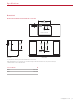
Specifications Downdraft INSTALLATION WITH STANDARD INSTALLED COOKTOP W DOWNDRAFT CUTOUT WIDTH 2 11/16" (68) E 8 1/4" (210)* COOKTOP CUTOUT TOP VIEW 8 1/4" (210)* 211/4" 211/4" 23 3/8" (540) (540) (594) E SIDE VIEW FRONT VIEW *6" (152) back from countertop cutout when internal blower is rear mounted. NOTE: Internal blower 6" (152) round, side, rear or bottom discharge. In-line and remote blower 10" (254) round, rear discharge. Centerline indicates center of downdraft cutout.
Specifications Downdraft INSTALLATION WITH FLUSH INSTALLED COOKTOP W DOWNDRAFT CUTOUT WIDTH 2 5/16" (59) E 8 1/4" (210)* COOKTOP CUTOUT TOP VIEW 8 1/4" (210)* 211/4" 211/4" 23 3/8" (540) (540) (594) E SIDE VIEW FRONT VIEW *6" (152) back from countertop cutout when internal blower is rear mounted. NOTE: Internal blower 6" (152) round, side, rear, or bottom discharge. In-line and remote blower 10" (254) round, rear discharge. Centerline indicates center of downdraft cutout.
Specifications Downdraft INSTALLATION WITH SEALED BURNER RANGETOP W DOWNDRAFT CUTOUT WIDTH 2 11/16" (68) E 8 1/4" (210)* RANGETOP OPENING TOP VIEW 19" (483) PLATFORM DEPTH 211/4" 211/4" 23 3/8" (540) (540) (594) 8 1/4" (210)* E SIDE VIEW FRONT VIEW *6" (152) back from countertop cutout when internal blower is rear mounted. NOTE: Internal blower 6" (152) round, side, rear, or bottom discharge. In-line and remote blower 10" (254) round, rear discharge.
Installation Installation DOWNDRAFT TRANSITION Install the top mounting brackets using the #4 sheet metal screws provided. Refer to the illustration below. For internal blowers, remove the existing 10" (254) round transition. Refer to the illustration below. Install the lower mounting brackets using the #8 x 32 sheet metal screws provided, but do not tighten. The brackets need to be adjusted once the downdraft is placed in the opening. Refer to the illustration below.
Installation Installation INTERNAL BLOWER To mount the internal blower on the front or rear of the downdraft: 1 2 Rotate the blower box so the 6" (152) round discharge is properly located, then disconnect the cable from the downdraft receptacle and connect it to the blower receptacle. Refer to the illustrations below. Once the blower connection is made and the discharge properly located, secure the blower to the downdraft using the four screws provided.
Installation Installation IN-LINE / REMOTE BLOWER COUNTERTOP MOUNTING 1 Insert the electrical supply (Romex®) from the in-line or remote blower through the opening on the downdraft and secure using an approved cord strain relief. 2 Connect hot to brown, neutral to blue, and ground to green. Refer to the illustrations below. Place the downdraft in the opening, then secure the bottom brackets to the cabinet base using the wood screws provided.
Installation Installation CONTROL MODULE 1 WARNING Use the template provided on the following page to mark the holes for the mounting screws. Drill one 13/4" (45) hole in the center and two 3/8" (10) holes for the mounting screws. CAUTION Verify the scale of the template if not using the installation guide shipped with the downdraft. 2 Check the countertop thickness to make sure the threaded studs are long enough to allow the thumbnuts to fully engage.
Installation Installation CONTROL MODULE TEMPLATE 13/16" (21) 2 9/16" (65) CL 2 9/16" (65) 13/16" (21) CL 0" 1" (25) SCALE wolfappliance.
Troubleshooting Troubleshooting IMPORTANT NOTE: If the downdraft does not operate properly, follow these troubleshooting steps: • Verify electrical power is supplied to the downdraft. • Verify proper electrical connections. • If the downdraft does not operate properly, contact Wolf Factory Certified Service. Do not attempt to repair the downdraft. Wolf is not responsible for service required to correct a faulty installation. 14 | Wolf Customer Care 800.222.
Sub-Zero, Sub-Zero & Design, Sub-Zero & Snowflake Design, Dual Refrigeration, The Living Kitchen, Great American Kitchens The Fine Art of Kitchen Design, Wolf, Wolf & Design, Wolf Gourmet, W & Design, red colored knobs, Cove, and Cove & Design are registered trademarks and service marks of Sub-Zero Group, Inc. and its subsidiaries. All other trademarks are property of their respective owners in the United States and other countries. wolfappliance.
Ventilación de tiro descendente Contenido Aviso importante 3 Ventilación de tiro descendente 4 Especificaciones Para garantizar que este producto se instale y opere de la forma más segura y eficiente posible, tome nota de los siguientes tipos de información resaltada en esta guía: 9 Instalación 14 Resolución de problemas Las características y especificaciones están sujetas a cambios sin previo aviso. Visite wolfappliance.com/specs para obtener la información más actualizada.
Ventilación de tiro descendente Información del producto La información importante del producto, incluidos el modelo y el número de serie de la unidad, se encuentra en la placa de datos del producto. La placa de datos se encuentra al lado de la cubierta del extractor en la parte frontal del tiro descendente, debajo del mostrador. Consulte la siguiente ilustración.
Especificaciones Requisitos de instalación Para instalarlo con una estufa Wolf, se necesita un mostrador plano de 251/8" (638) de profundidad. Para la instalación con un quemador sellado o una estufa contemporánea de 30" (762) o 36" (914), se necesita un kit de accesorios de ribetes. Póngase en contacto con su distribuidor autorizado de Wolf para obtener más información.
Especificaciones Instalación eléctrica La instalación debe tener una conexión a tierra de conformidad con los códigos locales o, en ausencia de códigos locales, con el Código Nacional de Electricidad, ANSI/ NFPA 70. Coloque el suministro eléctrico tal y como se muestra en las ilustraciones de las páginas 6–8. Es necesario un circuito independiente que dé servicio únicamente a este aparato.
Especificaciones Ventilador de tiro descendente INSTALACIÓN CON COCINERO INSTALADO ESTÁNDAR W ANCHURA DEL RECORTE PARA EL VENTILADOR DE TIRO DESCENDENTE 2 11/16" (68) E 8 1/4" (210)* RECORTE PARA ESTUFA VISTA SUPERIOR 8 1/4" (210)* 211/4" 211/4" 23 3/8" (540) (540) (594) E VISTA LATERAL VISTA FRONTAL *6" (152) detrás del recorte del mostrador cuando el extractor interno está montado en la parte posterior.
Especificaciones Ventilador de tiro descendente INSTALACIÓN CON COCINA INSTALADA EN LAVADO W ANCHURA DEL RECORTE PARA EL VENTILADOR DE TIRO DESCENDENTE 2 5/16" (59) E 8 1/4" (210)* RECORTE PARA ESTUFA VISTA SUPERIOR 8 1/4" (210)* 211/4" 211/4" 23 3/8" (540) (540) (594) E VISTA LATERAL VISTA FRONTAL *6" (152) detrás del recorte del mostrador cuando el extractor interno está montado en la parte posterior.
Especificaciones Ventilador de tiro descendente INSTALACIÓN CON ESTUFA CON QUEMADORES SELLADOS W ANCHURA DEL RECORTE PARA EL VENTILADOR DE TIRO DESCENDENTE 2 11/16" (68) E 8 1/4" (210)* ABERTURA PARA ESTUFA VISTA SUPERIOR 19" (483) PROFUNDIDAD DE LA PLATAFORMA 211/4" 211/4" 23 3/8" (540) (540) (594) 8 1/4" (210)* E VISTA LATERAL VISTA FRONTAL *6" (152) detrás del recorte del mostrador cuando el extractor interno está montado en la parte posterior.
Instalación Instalación VENTILADOR DE TIRO DESCENDENTE 1 2 Instale los soportes de montaje superior con los tornillos de metal #4 proporcionados. Consulte la siguiente ilustración. Instale los soportes de montaje inferior con los tornillos de metal #8 x 32 proporcionados, pero no los apriete. Los soportes deberán ajustarse una vez que el tiro descendente se encuentre en la abertura. Consulte la siguiente ilustración.
Instalación Instalación EXTRACTOR INTERNO Para montar el extractor interno al frente o en la parte de atrás del tiro descendente: 1 2 Gire la caja del extractor de tal manera que el escape circular de 6" (152) se encuentre en el lugar apropiado, a continuación desconecte el cable del receptáculo del tiro descendente y conéctelo al receptáculo del extractor. Consulte las siguientes ilustraciones.
Instalación Instalación EXTRACTOR EN LÍNEA / REMOTO MONTAJE DEL MOSTRADOR 1 Inserte el suministro eléctrico (Romex®) del extractor en línea o remoto por la abertura en el tiro descendente y asegúrelo con un liberador de tensión aprobado. 2 Conecte el cable de la corriente al cable marrón, el neutro al azul y la tierra al verde. Consulte la siguiente ilustración.
Instalación Instalación MÓDULO DE CONTROL 1 ADVERTENCIA Utilice la plantilla proporcionada en la página 13 para marcar los orificios para los tornillos de montaje. Taladre un orificio de 13/4" (45) en el centro y dos de 3/8" (10) para los tornillos de montaje. PRECAUCIÓN Verifique la escala de la plantilla si no va utilizar la guía de instalación enviada con el tiro descendente.
Instalación Instalación PLANTILLA DEL MÓDULO DE CONTROL 13/16" (21) 2 9/16" (65) CL 2 9/16" (65) 13/16" (21) CL 0" 1" (25) ESCALA SCALE wolfappliance.
Resolución de problemas Resolución de problemas AVISO IMPORTANTE: si el sistema de ventilación de tiro descendente no tiene un funcionamiento apropiado, siga estos pasos para resolver los problemas: • Compruebe que el tiro descendente tenga corriente eléctrica. • Compruebe que las conexiones eléctricas son las adecuadas. • Si el tiro descendente no funciona correctamente, póngase en contacto con el centro de servicio autorizado de Wolf. No intente reparar el tiro descendente.
Sub-Zero, Sub-Zero & Design, Sub-Zero & Snowflake Design, Dual Refrigeration, The Living Kitchen, Great American Kitchens The Fine Art of Kitchen Design, Wolf, Wolf & Design, Wolf Gourmet, W & Design, perillas de color rojo, Cove, and Cove & Design son marcas registradas y marcas de servicio de Sub-Zero Group, Inc. y sus asociados. Todas las demás marcas registradas son propiedad de sus dueños respectivos en los Estados Unidos y otros países. wolfappliance.
Ventilation à aspiration descendante Table des matières Remarque importante 3 Ventilation à aspiration descendante 4 Spécifications 9 Installation Pour s'assurer que ce produit est installé et utilisé en toute sécurité et aussi efficacement que possible, prenez note des types de renseignement mis en évidence tout au long de ce guide : 14 Dépannage Les caractéristiques et les spécifications peuvent être modifiées en tout temps sans préavis. Visitez wolfappliance.
Ventilation à aspiration descendante Renseignements sur le produit Des renseignements importants sur le produit, y compris les numéros de modèle et de série, se trouvent sur la plaque signalétique du produit. La plaque signalétique est située à côté du boîtier de la soufflerie sur le devant de l´aspiration descendante, sous le comptoir. Reportez-vous à l´illustration ci-dessous. Si vous avez besoin de service, communiquez avec le service Wolf certifié par l’usine avec les numéros de modèle et de série.
Spécifications Exigences d´installation Pour l´installation avec une surface de cuisson Wolf, un comptoir plat d´au moins 251/8 po (638) de profondeur est requis. Pour installation avec un plan de cuisson scellé ou une table de cuisson contemporaine de 30 po (762) ou 36 po (914), une trousse de garniture accessoire est requise. Communiquez avec votre dépositaire Wolf autorisé pour de plus amples renseignements.
Spécifications Électricité L´installation doit être mise à la terre électriquement conformément aux codes locaux ou, en l´absence de codes locaux, conformément au code national de l´électricité, ANSI/NFPA 70. Repérez l´alimentation électrique, comme il est montré dans les illustrations aux pages 6–8. Un circuit séparé servant uniquement cet appareil est requis. Un disjoncteur de fuite de terre (GFCI) n´est pas recommandé et peut interrompre le fonctionnement.
Spécifications Aspiration descendante INSTALLATION AVEC LA TABLE DE CUISSON INSTALLEE STANDARD L LARGEUR DE LA DÉCOUPE DE L’ASPIRATION DESCENDANTE 2 11/16 po (68) E 8 1/4 po (210)* DÉCOUPE DE LA SURFACE DE CUISSON VUE DE DESSUS 8 1/4 po 211/4 po 211/4 po 23 3/8 po (210)* (540) (540) (594) E VUE DE PROFIL VUE DE FACE *6 po (152) de l’arrière de la découpe du comptoir lorsque la soufflerie interne est installée à l’arrière.
Spécifications Aspiration descendante INSTALLATION AVEC LA TABLE DE CUISSON INSTALLEE DE FLUSH L LARGEUR DE LA DÉCOUPE DE L’ASPIRATION DESCENDANTE 2 5/16 po (59) E 8 1/4 po (210)* DÉCOUPE DE LA SURFACE DE CUISSON VUE DE DESSUS 8 1/4 po 211/4 po 211/4 po 23 3/8 po (210)* (540) (540) (594) E VUE DE PROFIL VUE DE FACE *6 po (152) de l’arrière de la découpe du comptoir lorsque la soufflerie interne est installée à l’arrière.
Spécifications Aspiration descendante INSTALLATION AVEC DESSUS DE CUISINIÈRE À BRÛLEUR SCELLÉ L LARGEUR DE LA DÉCOUPE DE L’ASPIRATION DESCENDANTE 2 11/16 po (68) E 8 1/4 po (210)* OUVERTURE DU DESSUS DE CUISINIÈRE VUE DE DESSUS 19 po (483) PROFONDEUR DE LA PLATE-FORME 211/4 po 211/4 po 23 3/8 po (540) (540) (594) 8 1/4 po (210)* E VUE DE PROFIL VUE DE FACE *6 po (152) de l’arrière de la découpe du comptoir lorsque la soufflerie interne est installée à l’arrière.
Installation Installation ASPIRATION DESCENDANTE TRANSITION 1 Installez les supports de montage supérieurs au moyen des vis autotaraudeuses n° 4 fournies. Reportez-vous à l´illustration ci-dessous. our les souffleries internes, retirez la transition ronde P existante de 10 po (254). Reportez-vous à l´illustration ci-dessous. 2 Installez les supports de montage inférieurs en utilisant les vis autotaraudeuses n° 8 x 32 fournies, mais ne serrez pas.
Installation Installation SOUFFLERIE INTERNE our installer la soufflerie interne sur l´avant ou l´arrière P de l´aspiration descendante : 1 2 Pivotez la boîte de la soufflerie afin que l´évacuation ronde de 6 po (152) soit correctement placée, puis débranchez le câble de la prise de l´aspiration descendante et branchez-le sur la prise de la soufflerie. Reportez-vous aux illustrations ci-dessous.
Installation Installation SOUFFLERIE EN LIGNE / À DISTANCE MONTAGE SUR UN COMPTOIR 1 Insérez l´alimentation électrique (Romex®) de la soufflerie en ligne ou à distance dans l´ouverture de l´aspiration descendante et fixez au moyen d´un cordon approuvé comme réducteur de tension. 2 Reliez le fil chaud au brun, le fil neutre au bleu et la mise à la terre au vert. Reportez-vous à l´illustration ci-dessous. CHAUD Fixez les supports de montage supérieurs au comptoir au moyen des vis à bois fournies.
Installation Installation MODULE DE COMMANDE 1 AVERTISSEMENT Utilisez le gabarit fourni à la page 13 pour marquer les trous pour les vis de montage. Percez un trou de 13/4 po (45) au centre et deux trous de 3/8 po (10) pour les vis de montage. MISE EN GARDE Vérifiez l´échelle sur le gabarit si vous n´utilisez pas le guide d´installation expédié avec l´aspiration descendante.
Installation Installation GABARIT DU MODULE DE COMMANDE 13/16 po (21) 2 9/16 po (65) CL 2 9/16 po (65) 13/16 po (21) CL 0 po 1 po (25) ÉCHELLE wolfappliance.
Dépannage Dépannage REMARQUE IMPORTANTE : si le système de ventilation à aspiration descendante ne fonctionne pas correctement, suivez ces étapes de dépannage : • Assurez-vous que l´aspiration descendante est alimentée. • Vérifiez les connexions électriques. • Si l´aspiration descendante ne fonctionne pas correctement, communiquez avec le service Wolf certifié par l´usine. Ne tentez pas de réparer l´aspiration descendante.
Sub-Zero, Sub-Zero & Design, Sub-Zero & Snowflake Design, Dual Refrigeration, The Living Kitchen, Great American Kitchens The Fine Art of Kitchen Design, Wolf, Wolf & Design, Wolf Gourmet, W & Design, les boutons de couleur rouge, Cove et Cove & Design sont des marques déposées et de service de Sub-Zero Group, Inc. et ses filiales. Toutes les autres marques de commerce appartiennent à leurs propriétaires respectifs aux États-Unis et dans d'autres pays. wolfappliance.
WOLF APPLIANCE, INC. P.O. BOX 44848 MADISON, WI 53744 823417 REV-A 4 / 2021 WOLFAPPLIANCE.COM 800.222.