
Inline Blower Install


Page 2
10” ROUND
DUCT
CEILING JOIST
(24” centers
shown)
2 X 4 FRAMING
(wide side down)
MOUNTING
BRACKETS
(Attached to
opposite sides
of housing &
upside-down,
so housing is
flush with
finished ceiling)
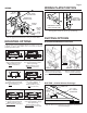
DUCTING (Horizontal blower discharge)
Two ways to connect ductwork to a factory-shipped unit.
ROOF CAP
10”
ROUND
ELBOW
10”
ROUND
DUCT
WALL
CAP
MOUNTING
SCREW
4½” X 18½”
TO 10” ROUND
TRANSITION
4½” X 18½”
TO 10” ROUND
TRANSITION
10” ROUND
DUCT
4½” X 18½” TO 10”
ROUND TRANSITION
10”
ROUND
DUCT
MOUNTING USING HANGER KIT (included)
Blower factory-shipped in straight-through
discharge position.
TYPICAL INSTALLATION
Blower factory-shipped in straight-through
discharge position.
IMPORTANT: Remove shipping tape from damper
Remove the shipping tape from the damper flap and make sure that
damper flap opens and closes freely inside the ductwork. Use duct
tape to make ductwork connections secure and air-tight.
ACCESS
PANEL
ACCESS
PANEL SCREW
GRILLE NUT
(Install into
square holes in
housing)
MOUNTING
BRACKET
10” ROUND
DUCT
(OUTLET)
10” ROUND
DUCT (INTAKE)
HANGER
KIT NUT &
WASHER
HANGER
KIT BOLT
& WASHER
HANGER
KIT
EYE-BOLT
HANGER
KIT CHAIN
TYPICAL INSTALLATION
MOUNTING (New Frame Construction)
CEILING
JOIST
(24” centers
shown)
10” ROUND DUCT
Factory-shipped unit installed in new construction.
MOUNTING
SCREW
Blower factory-shipped
in horizontal
discharge position.
Mounting brackets
factory-shipped in
position for ½” ceil-
ing material.
MOUNTING (Existing Frame Construction)
4½” X 18½”
TO 10” ROUND
TRANSITION
10” ROUND
DUCT
4½” X 18½”
TO 10” ROUND
TRANSITION
EXTENSION
SPRING
4½” X 18½”
TO 10”
ROUND
TRANSI-
TION